Archive for March 2013

Understand appropriate use cases for CPU affinity

magnet

What is CPU Affinity?

By specifying a CPU affinity setting for each virtual machine, you can restrict the assignment of virtual machines to a subset of the available processors in multiprocessor systems. By using this feature, you can assign each virtual machine to processors in the specified affinity set.

CPU affinity specifies virtual machine-to-processor placement constraints and is different from the relationship created by a VM-VM or VM-Host affinity rule, which specifies virtual machine-to-virtual machine host placement constraints.
In this context, the term CPU refers to a logical processor on a hyperthreaded system and refers to a core on a non-hyperthreaded system.

The CPU affinity setting for a virtual machine applies to all of the virtual CPUs associated with the virtual machine and to all other threads (also known as worlds) associated with the virtual machine. Such virtual machine threads perform processing required for emulating mouse, keyboard, screen, CD-ROM, and miscellaneous legacy devices.

By setting a CPU affinity on the virtual machine you are limiting the available CPUs on which the virtual machine can run. It does not dedicate that CPU to that virtual machine and therefore does not restrict the CPU scheduler from using that CPU for other virtual machines

Problems with CPU Affinity

In some cases, such as display-intensive workloads, significant communication might occur between the virtual CPUs and these other virtual machine threads. Performance might degrade if the virtual machine’s affinity setting prevents these additional threads from being scheduled concurrently with the virtual machine’s virtual CPUs. Examples of this include a uniprocessor virtual machine with affinity to a single CPU or a two-way SMP virtual machine with affinity to only two CPUs.

Consider your resource management needs before you enable CPU affinity on hosts using hyperthreading. For example, if you bind a high priority virtual machine to CPU 0 and another high priority virtual machine to CPU 1, the two virtual machines have to share the same physical core. In this case, it can be impossible to meet the resource demands of these virtual machines. Ensure that any custom affinity settings make sense for a hyperthreaded system

For the best performance

When you use manual affinity settings, VMware recommends that you include at
least one additional physical CPU in the affinity setting to allow at least one of the virtual machine’s threads to be scheduled at the same time as its virtual CPUs. Examples of this include

  • A uniprocessor virtual machine with affinity to at least two CPUs
  • A two-way SMP virtual machine with affinity to at least three CPUs

Assign a Virtual Machine to a Specific Processor
Using CPU affinity, you can assign a virtual machine to a specific processor. This allows you to restrict the assignment of virtual machines to a specific available processor in multiprocessor systems.
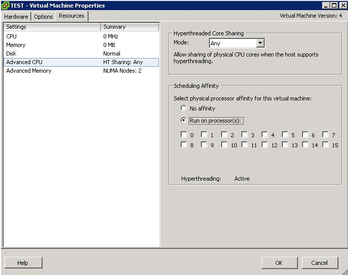
Procedure

  • In the vSphere Client inventory panel, select a virtual machine and select Edit Settings.
  • Select the Resources tab and select Advanced CPU
  • Click the Run on processor(s) button
  • Select the processors where you want the virtual machine to run and click OK
  • If you cannot see this option, it is because the host is in a DRS Cluster, the CPU affinity “Run on processor” feature  is not availble as its the DRS that manages ressources!

affinity

Use cases for CPU Affinity

  • Cisco’s Unity

Cisco Unity messaging is a real-time application, which makes it more difficult to virtualize than traditional data-centric applications, such as database and email servers. (For example, to support 144 concurrent voice sessions, Cisco Unity messaging must place 7,200 packets on the wire at a precise 20 ms interval.) Delivering this level of performance in a reliable, predictable, and serviceable manner requires some concessions, primarily surrounding CPU Affinity

Read this article on CPU Affinity

http://frankdenneman.nl/2011/01/11/beating-a-dead-horse-using-cpu-affinity/

Installing ESXi 5.1 as a VM on an ESXi 5.1 Host

images

Installing ESXi 5.1 as VM on an ESXi 5.1 Host

This article explains how to install VMware ESXi in a virtual machine. Installing ESXi in a virtual machine provides a way to try the product without dedicating hardware to it. A virtual ESXi machine may be useful if you are studying to become a VCP (VMware Certified Professional)

Nested Virtualisation Check

A quick way to verify whether your CPU truly supports both Intel-VT+EPT or AMD-V+RVI, you can paste the following into a browser:

https://[your-esxi-host-ip-address]/mob/?moid=ha-host&doPath=capability

You will need to login with your root credentials and then look for the “nestedHVSupported” property and if it states false, it means you maybe able to install nested ESXi or other hypervisor, but you will not be able to run nested 64-bit VMs, only 32-bit VMs, assuming you have either Intel-VT or AMD-V support on your CPUs.

Capture

  • Intel VT-x or AMD-V is required for running “Nested Virtualization” which supports nested 32-bit VMs
  • Intel EPT or AMD RVI is required for running nested 64-bit VMs

Instructions

  • Download the ESXi 5.1 ISO image from the VMware Download site
  • Log into your physical host with the vClient
  • Click on your Physical Host
  • Select Create Virtual Machine
  • Select Custom
  • Type a name for your Virtual ESXI 5.1 Host
  • Choose a Datastore
  • Select Virtual Machine Version 8
  • Choose Linux > Red Hat Enterprise Linux 6 (64bit)
  • Choose 2 Virtual Sockets and 1 core per virtual socket
  • Choose 2 or 4GB RAM
  • Choose your network
  • Choose your SCSI Controller. LSI Logic SAS is probably the best one to choose
  • Select a Create a new Virtual Disk
  • Select Disk size.
  • Choose your Disk Provisioning Method. Thick Provisioned Lazy Zero is ok
  • Select Store with the Virtual Machine
  • Choose Advanced Options. These can probably be left as they are
  • Next > Finish
  • When the VM is built, click Edit Settings
  • Attach your VMware ESXi 5.1 ISO to the VMs CD Drive and select to Connect at Power On
  • This next option is critical to allow a virtual machine to power on within the virtualized ESXi system. The advanced option “monitor_control.restrict_backdoor” with a value of “True” must be added to the virtual machine’s general options. The configuration parameters section is empty on the virtual machine at this point because it has not been created yet. If you have ever been in this section of the virtual machine configuration for a virtual machine that already exists, there are a number of options that are populated.
  • If you are using an i3 or later processor (that is, you do not have a Core 2 Duo), you can enable nested VT. This allows you to run 64bit virtual machines within ESXi. To enable nested VT, add this line – vhv.enable = “TRUE” to the .vmx file of the ESXi virtual machine:
  • Start the VM
  • Press Enter to start the boot process
  • Press fn+F11 to accept the EULA and continue
  • Select the virtual drive where you want to install. Press Enter to continue
  • Select a keyboard layout. Press Enter to continue.
  • Enter a root password. Press the down arrow key, then enter the password again to confirm. Press Enter to continue
  • This warning appears: <HARDWARE_VIRTUALIZATION WARNING: Hardware Virtualization is not a feature of the CPU, or is not enabled in the BIOS> This is generally expected. Press Enter to carry on
  • Confirm that the info on the screen is correct then press F11 to install
  • Reboot when required and remove the attached ISO
  • If virtual machines on the virtual ESXi server are going to be powered on, the Enable Promiscuous Mode option will need to be enabled on the vSwitch on which the virtual ESXi server resides.
  • The ESXi guest starts with an IP address assigned from DHCP. To set a static IP address: Press fn+F2.
  • Enter your password, then press Enter.
  • Select Configure Management Network, then press Enter.
  • Select IP Configuration, then press Enter.
  • Select Set static IP addresses and network configuration, then press the space bar.
  • Press the down arrow key to select IP Address field, then enter the correct information.
  • If you need to set the Subnet or Default Gateway, press the down arrow key to select those fields.
  • After you have finished adjusting the settings, press Enter to exit.
  • Press ESC to exit the configuration screen.
  • When you are prompted to restart the management network for the changes to take effect, press Y.
  • Press ESC again to go back to the main screen.

Running Hyper V

  • Edit your Virtual Switch and enable Promiscuous Mode
  • Upgrade your Hyper V VM to Hardware Version 9
  • Use WinSCP to tweak the hyperv.vmx file
  • guestOS = “winhyperV”
  • featMask.vm.hv.capable = “Min:1” followed by a carriage return
  • Save Changes

Configure an Auto Deploy Reference Host

Cloud

Introduction

In an environment where no state is stored on the host, a reference host helps you set up multiple hosts with the same configuration. You configure the reference host with the logging, coredump, and other settings that you want, save the host profile, and write a rule that applies the host profile to other hosts as needed.

You can configure the storage, networking, and security settings on the reference host and set up services such as syslog and NTP. The exact setup of your reference host depends on your environment, but you might consider the following customization.

custom

Auto Deploy Reference Host Setup

custom

Configuring an Auto Deploy Reference Host

  • vSphere Client

The vSphere Client supports setup of networking, storage, security, and most other aspects of an ESXi host. You can completely set up your environment and export the host profile for use by Auto Deploy.

  • vSphere Command Line Interface

You can use vCLI commands for setup of many aspects of your host. vCLI is especially suitable for configuring some of the services in the vSphere environment. Commands include vicfg-ntp (set up an NTP server), esxcli system syslog (set up a syslog server), and vicfg-route (set up the default route).

  • Host Profile Interface

You can either set up a host with vSphere Client or vCLI and save the host profile for that host, or you can configure the host profiles directly with the Host Profiles interface in the vSphere Client

Provision/Reprovision ESXi Hosts using AutoDeploy

index

Provisioning and Reprovisioning

Provisioning a host that has never been provisioned with Auto Deploy (first boot) differs from subsequent boot processes. You must prepare the host, define the image using the Image Builder PowerCLI, and fulfill all other prerequisites before you can provision the host.

vSphere Auto Deploy supports multiple reprovisioning options. You can perform a simple reboot or reprovision with a different image or a different host profile.

Provisioning for the first time

Capture2

Subsequent boot of an AutoDeployed ESXi Host

depot

Reprovisoning

vSphere Auto Deploy supports multiple reprovisioning options. You can perform a simple reboot or reprovision with a different image or a different host profile.

The following reprovisioning operations are available.

  • Simple reboot.
  • Reboot of hosts for which the user answered questions during the boot operation.
  • Reprovision with a different image profile.
  • Reprovision with a different host profile.

Test and Repair Rule Compliance

  • When you add a rule to the Auto Deploy rule set or make changes to one or more rules, unprovisioned hosts that you boot are automatically provisioned according to the new rules. For all other hosts, Auto Deploy applies the new rules only when you test their rule compliance and perform remediation.
    This task assumes that your infrastructure includes one or more ESXi hosts provisioned with Auto Deploy, and that the host on which you installed VMware PowerCLI can access those ESXi hosts.

Prerequisites

  • Install VMware PowerCLI and all prerequisite software.
  • If you encounter problems running PowerCLI cmdlets, consider changing the execution policy.

Procedure changing the host profile used in the rule

  • Check which Auto Deploy rules are currently available. The system returns the rules and the associated items and patterns
  • Get-DeployRule
  • Make a change to one of the available rules, for example, you might change the image profile and the name of the rule. You cannot edit a rule already added to a rule set. Instead, you copy the rule and replace the item you want to change.
  • Copy-DeployRule -DeployRule testruleimageprofile -ReplaceItem DACVESX002_Host_Profile
  • Verify that the host that you want to test rule set compliance for is accessible.
    Get-VMHost -Name 10.1.1.100
  • Test the rule set compliance for that host and bind the return value to a variable for later use.
  • $tr = Test-DeployRuleSetCompliance 10.1.1.100
  • Examine the differences between what is in the rule set and what the host is currently using $tr.itemlist The system returns a table of current and expected items.
  • Remediate the host to use the revised rule set the next time you boot the host.
  • Repair-DeployRuleSetCompliance $tr

deployrulescompliance

What to do next

If the rule you changed specified the inventory location, the change takes effect immediately. For all other changes, boot your host to have Auto Deploy apply the new rule and to achieve compliance between the rule set and the host.

Please see Pages 81-85 of the vSphere Installation and Setup Guide

Configure Bulk Licensing

images

You can use the vSphere Client or ESXi Shell to specify individual license keys, or you can set up bulk licensing by using PowerCLI cmdlets. Bulk licensing works for all ESXi hosts, but is especially useful for hosts provisioned with Auto Deploy.

Assigning license keys through the vSphere Client or assigning licensing by using PowerCLI cmdlets functions differently as shown in the table below

license

Procedure

lic

Demo

  • Connect to vCenter and create the following 2 variables
  • $licenseDataManager = Get-LicenseDataManager
  • $hostContainer = Get-DataCenter -Name DataCenterName

bulklicense

  • Note this is as far as I can go as I don’t have any license keys 🙂

Installing Microsoft Failover Clustering on VMware vSphere 4.1 with RDMs

This is a quick guide to installing Microsoft Failover Clustering on VMware vSphere 4.1 on 2 VMs across the 2 hosts

Pre-Requisites

  • Failover Clustering feature is available with Windows Server 2008/R2 Enterprise/Data Center editions. You don’t have this feature with the Standard edition of Windows Server 2008/R2
  • You also need a form of Shared Storage (FC)
  • To use the native disk support included in failover clustering, use basic disks, not dynamic disks and format as NTFS
  • Setup 1 Windows 2008 R2 Domain Controller Virtual Machine with Active Directory Services and a Domain
  • Setup 1 x Windows Server 2008 R2 Virtual Machine for Node 1 of the Windows Cluster with 2 NICs
  • Setup 1 x Windows Server 2008 R2 Virtual Machine for Node 2 of the Windows Cluster with 2 NICs

Instructions

  • Make sure all Virtual Machine are joined to the domain
  • Make sure all Virtual Machines are fully updated and patched with the latest S/W updates
  • You may need to adjust your Windows Firewall
  • On the first network adapter rename this as Public and on the second adapter, rename this as Private or MSCS Heartbeat
  • On the first network adapter, add the static IP address, Subnet Mask, Gateway and DNS
  • On the second network adapter, just add the IP Address and Subnet Mask
  • Go back to the original screen and untick the following boxes
  • Clear the Client for Microsoft Networks
  • Clear the File and Printer Sharing
  • Clear QOS Packet Scheduler
  • Clear Link Layer Toplogy checkboxes

Link Layer

  • Click Properties on Internet Protocol Version 4 (TCP/IPv4)

  • Click the DNS tab and clear the Register this Connection’s Addresses in DNS

DNS

  • Select the WINS tab and clear the Enable LMHOSTS Lookup checkbox

LMHOSTS

  • After you configured the IP addresses on every network adapter verify the order in which they are accessed. Go to Network Connections click Advanced > Advanced Settings and make sure that your LAN connection is the first one. If not click the up or down arrow to move the connection on top of the list. This is the network clients will use to connect to the services offered by the cluster.

BINDING

Adding Storage

I am assuming that your Storage Admin has already pre-created the LUNs that we are going to assign

  •  Go to vCenter and click Edit Settings
  • Select Add > Select Hard Disk

adddisks

  • Select Raw Device Mapping

rdm1

  • You will see that there are 4 LUNs available. This is because I want to set up Microsoft Failover Clustering with SQL Failover clustering and I need 4 disks for the Quorum, SQL Data, SQL Logs and MSDTC

RDM2

  • Select to store with the Virtual Machine. When an RDM is used, a small VMDK file is created on a VMFS Datastore and is a pointer to the RDM. This will be used when you configure the 2nd node in the cluster

rdm3a

  • Select Compatibility Mode. Physical Compatibility Mode is required for Microsoft Failover Cluster across hosts

rdm4

  • Review and Finish
  • Because you added the new disk as a new device on a new bus, you now have a new virtual SCSI controller which will default to the recommended type, LSI Logic SAS for Windows 2008 and Windows 2008 R2

rdm5

  • In Edit Settings, you need to click on the newly created SCSI Controller and select Physical for SCSI Bus Sharing. This is required for failover clustering to detect the storage as usable

rdm6

  • You now need to repeat this action for all RDMs you need to add
  • When you have finished adding all the RDMs you should see the following in Edit Settings for the VM

rdm7

  • You should now have the following setup to work with

RDM8

  • Next we need to add the RDMs to the second VM which is a slightly different procedure
  • Click Edit Settings on the 2nd VM and Add Hard Disk

adddisks

  • Select Choose and existing Virtual Disk

rdm9

  • To select the RDM Pointer file browse to the datastore and folder for the VM where you created the pointer file on the first VM

rdm10a

  • Select the same SCSI Virtual Device Node you setup on the first VM for the first RDM

rdm11

  • Review Settings and make sure everything is correct

RDM12

  • Next you will need to set the SCSI Bus Sharing Mode to Physical and verify that the type is LSI Logic SAS

rdm13

  • You now need to do the same for all the disks that have been added
  • Check everything looks correct and this is your storage setup

Configuring the storage on the VMs

  • Power on Node/VM1
  • Connect to Node1/VM1
  • Launch Server Manager and navigate to Disk Management under Storage
  • In Disk Manager you will see the new disks as being offline
  • Right click each disk and select Online and if necessary right click again and select Initialise Disk then select the MBR partition type
  • Create a simple volume on all 4 disks which should then look like the below

Disks

  • Next Power on and log into Node2/VM2
  • Open Disk Management and right click each disk and select Online. Once the Disks are online you will see the volume labels and status
  • If the disks have been assigned the next available drive letters then you will need to change the drive letters to match the letters you assigned on Node1/VM1
  • The disks will now look identical to Node1/VM1

Install Microsoft Failover Clustering

You will need to install Failover Clustering on both nodes as per below procedure

  • Open Server Manager > Add Features > Failover Clustering

cluster1

  • Click Install

cluster2

  • On the first Node1/VM1 click Start > Administrative Tools > Failover Cluster Manager
  • Click on Validate a Cluster

cluster3

  • Validation will run a variety of tests against your virtual hardware including the storage and networking to verify if the hardware is configured correctly to support a failover cluster. To pass all tests, both nodes must be online and the hardware must be configured correctly

cluster4

  • Select your 2 Nodes/VMs

cluster5

  • Click Next and Run all Tests

cluster6

  • Verify the server names and check the tests

cluster7

  • Click Run and the tests will begin

cluster8

  • Your configuration is now validated and you can check the reports for anything which is incorrect

cluster9

  • Click Create the cluster now using the validated nodes

cluster10

  • Type a name for your cluster
  • Type an IP Address for the Cluster IP

cluster11

  • Check details are all correct and click Create

cluster12

  • Finish and check everything is setup OK

cluster13

  • If you want to install SQL Server clustering, we will need to install a MSDTC Service
  • Go to Services and Applications – right click and select “Configure a service or application

CLUSTER14

  • Click Next and select DTC

cluster15

  • Put in a name and IP Address for the DTC

CLUSTER16

  • Click Next and select the storage you created for the MSDTC

cluster17

  • Click Next and Review the confirmation

cluster18

  • Click Next and the MSDTC Service will be created

cluster19

  • Finish and make sure everything was setup successfully

cluster20

  •  Congratulations, you have now set up your Windows Failover Cluster
  • Check that your Windows Cluster IP and your MSDTC IP are listed in DNS

To set up SQL Server Failover Clustering

http://www.electricmonk.org.uk/2012/11/13/sql-server-2008-clustering/

Utilise AutoDeploy cmdlets to deploy ESXi Hosts

index

Introduction

When you start a physical host set up for Auto Deploy, Auto Deploy uses a PXE boot infrastructure in conjunction with vSphere host profiles to provision and customize that host. No state is stored on the host itself, instead, the Auto Deploy server manages state information for each host.

  • The ESXi host’s state and configuration is run in memory
  • When the host is shutdown the state information is cleared from memory
  • Based on PXE Boot environments
  • Works with Image Buillder, vCenter Server and Host Profiles
  • Eliminates the need for a boot device
  • Common image across all hosts

With Autodeploy the previous boot device information is stored on the host and managed by vCenter

Image

Autodeploy Architecture

Capture

What does what?

Capture

 Rules engine

You specify the behavior of the Auto Deploy server by using a set of rules written in Power CLI. The Auto Deploy rule engine checks the rule set for matching host patterns to decide which items (image profile, host profile, or vCenter Server location) to provision each host with.

PowerCLI cmdlets are used to set, evaulate and update image profile and host profile rules

The Rules engine maps software images and host profiles to hosts based on the attributes of the host. For example

  • Rules can be based on IP or MAC Address
  • The -AllHosts option can be used for every host

What’s in the Rules engine?

Capture

What else is required?

req

Boot Process

process

AutoDeploy First Boot Process

Capture

AutoDeploy cmdlets

cmdlets

 Procedure

  • Log into PowerCLI and follow the below steps
  • Note to be careful with syntax and case sensitivity

Capture2

Demo

  • Log into PowerCLI
  • Type add-esxsoftwaredepot E:\Depot\VMware-ESXi-5.1.0-799733-depot.zip
  • Type get-esximageprofile
  • Type new-deployrule -name testruleimageprofile – item VMware-ESXi-5.1.0-799733-standard -allhosts

The above commands will add a software depot, get the ESXi image profiles then create a deployment rule named “testruleimageprofile” and will use the “VMware-ESXi-5.1.0-799733-standard” image profile or type in the customprofile you have created and will apply the rule to “Allhosts” or any ESXi host boots from it.

depot

  • Or
  • Log into PowerCLI
  • Type add-esxsoftwaredepot E:\Depot\VMware-ESXi-5.1.0-799733-depot.zip
  • Type get-esximageprofile
  • Type new-deployrule -name testruleimageprofile – item “ESXi-5.1.0-799733-standard”,”Cluster”,”DACVESX001 Host Profile” -pattern “ipv4=10.1.1.100-10.1.1.105”

The above commands will add a software depot, get the ESXi image profiles then create a deployment rule named “testruleimageprofile” and will use the “VMware-ESXi-5.1.0-799733-standard” image profile,  The Cluster Name “Cluster” and the Host Profile Name DACVESX001 Host Profile with a pattern to apply this to the IP range 10.1.1.100-10.1.1.105

autodeploynewrule

  • Click Enter and you should see the following screen appear

Capture

  • Add the second cluster rule

depot3

  • Once the deployment rules have been created successfully, add them to the working rule set by using the Add-DeployRule cmdlet. The following example adds the two deployment rules created previously to the working rule set
  • Add the Rules to the Working Rule Set
  • By default deploy rules are added to the active rule set. You add rules to the working rule set by including the -NoActivate flag when using the Add-DeployRule cmdlet.

depot2

  • Use the Get-DeployRuleSet to verify the rules were created

depot4

  • When the deployment rules have been added to the working rule set successfully, vSphere Auto Deploy will commence copying VIBs to the Auto Deploy server as required. In our case the VIBs associated with Brocade will be copied
  • Type Exit to Quit PowerCLI

Install the Auto Deploy Server

robot

What is Auto Deploy?

vSphere Auto Deploy can provision hundreds of physical hosts with ESXi software. You can specify the image to deploy and the hosts to provision with the image. Optionally, you can specify host profiles to apply to the hosts, and a vCenter Server folder or cluster for each host.

When a physical host set up for Auto Deploy is turned on, Auto Deploy uses a PXE boot infrastructure in conjunction with vSphere host profiles to provision and customize that host. No state is stored on the host itself. Instead, the Auto Deploy server manages state information for each host

Auto Deploy stores the information for the ESXi hosts to be provisioned in different locations. Information about the location of image profiles and host profiles is initially specified in the rules that map machines to image profiles and host profiles. When a host boots for the first time, the vCenter Server system creates a corresponding host object and stores the information in the database.

AutoDeploy Requirements

  • DHCP
  • DHCP Option 66: FQDN or IP Address of TFTP Server
  • DHCP Option 67: udionly.kpxe.vmw-hardwired – Name of GPXE Config file which we need the TFTP Server to direct the host to
  • Router Configuration – A setting to allow the DHCP
  • PXE
  • TFTP

Installation Instructions

  • Attach the vCenter ISO
  • Select AutoDeploy

Autodeploy1

  • Click Next

Autodeploy2

  • Click Next to the End User Patent Agreement

Autodeploy3

  • Click I accept to the Licensing agreement

Autodeploy4

  • Check Auto Deploy repository directory and repository maximum size

Autodeploy5

  • Put in vCenter Information

Autodeploy6

  • Trust the SSL Certificate

Autodeploy7

  • Check the ports

Autodeploy8

  • Check how your server is identified on the network

Autodeploy9

  • nn

Autodeploy10

  • Finish

Configure Advanced Boot Loader and Kernel Options

LogIcon

You can quickly deploy ESXi hosts using scripted, unattended installations or upgrades. Scripted installations, upgrades, or migrations provide an efficient way to deploy multiple hosts.
The installation or upgrade script contains the installation settings for ESXi. You can apply the script to all hosts that you want to have a similar configuration.

The installation or upgrade script can reside in one of the following locations:

  • FTP
  • HTTP/HTTPS
  • NFS
  • USB flash drive
  • CDROM

Enter Boot Options to Start an Installation or Upgrade Script

You can start an installation or upgrade script by typing boot command-line options at the boot command line.
At boot time you might need to specify options to access the kickstart file.

Procedure

  • You can enter boot options by pressing Shift+O in the boot loader.
  • For a PXE boot installation, you can pass options through the kernelopts line of the boot.cfg file.

KS

  • At the runweasel command prompt, type ks=location of installation script plus boot command line options
  • Example: ks=http://192.168.0.10/kickstart/ks_test.cfg nameserver=192.168.0.100 ip=192.168.0.210 netmask=255.255.255.0 gateway=192.168.0.254

The ESXi installer includes a default installation script that performs a standard installation to the first detected disk.

The default ks.cfg installation script is located in the initial RAM disk at /etc/vmware/weasel/ks.cfg. You can specify the location of the default ks.cfg file with the ks=file://etc/vmware/weasel/ks.cfg boot option

To get an idea how things work without writing installation script etc. Try installing a (virtual) ESXi host with the default ks.cfg installation script. At the weasel prompt, type:

ks=file://etc/vmware/weasel/ks.cfg

Kernel Options

The boot loader configuration file boot.cfg specifies

  • The kernel
  • The kernel options
  • The boot modules that the mboot.c32 boot loader uses in an ESXi installation.

The boot.cfg file is provided in the ESXi installer. You can modify the kernelopt line of the boot.cfg file to specify the location of an installation script or to pass other boot options.

This is useful while:

  • Creating an Installation .ISO with a custom installation or upgrade script;
  • Working with PXE booting the ESXi installer, using PXELINUX and a PXE or isolinux.cfg PXE configuration file.

Boot.cfg

The commands in boot.cfg configure the boot loader.

Capture

Identify ESXi Image Builder requirements

images

What is ESXi Image Builder CLI?

The ESXi Image Builder CLI is a set of PowerCLI cmdlets that you can use to manage vSphere image profiles and VIB packages, such as driver VIBs and update VIBs. You can also use Image Builder cmdlets to export an image profile to an ISO or offline depot ZIP file that you can use to install ESXi with a customized set of updates, patches, and drivers.

  • Manage software depots
  • Manage image profiles
  • Manage Software packages (VIBs).
  • Image profiles and VIBs specify the software you want to use during installation or upgrade of an ESXi host.

ESXi Image Builder Requirements

  • Microsoft .NET 2.0
  • Microsoft PowerShell 1.0 or 2.0
  • vSphere PowerCLI (includes Image Builder cmdlets)
  • Turn off IE ESC in Server Manager – Allows you to download TFTP Boot Zip file and AutoDeploy Log Files

Image Builder Overview

You use Image Builder cmdlets for managing the software to deploy to your ESXi hosts in several different scenarios.

scenario

The Image Builder PowerCLI cmdlets take image profiles and VIBs as input and produce different outputs.

inputoutput

Image Builder Architecture

Imagebuilder3

Terms and Definitions

VIB

Requirements

You can create a custom image profile from scratch or clone an existing profile and add or remove VIBs. A profile must meet the following requirements to be valid.

  • Each image profile must have a unique name and vendor combination.
  • Each image profile has an acceptance level. When you add a VIB to an image profile with an Image Builder PowerCLI cmdlet, Image Builder checks that the VIB matches the acceptance level defined for the profile.
  • You cannot remove VIBs that are required by other VIBs.
  • You cannot include two versions of the same VIB in an image profile. When you add a new version of a VIB, the new version replaces the existing version of the VIB.

Image Profile Validation

An image profile and its VIBs must meet several criteria to be valid.

  • Image profiles must contain at least one base VIB and one bootable kernel module
  • If any VIB in the image profile depends on another VIB, that other VIB must also be included in the image profile. VIB creators store that information in the SoftwarePackage object’s Depends property.
  • VIBs must not conflict with each other. VIB creators store conflict information in the SoftwarePackage object’s Conflicts property.
  • Two VIBs with the same name, but two different versions, cannot coexist. When you add a new version of a VIB, the new version replaces the existing version of the VIB.
  • No acceptance level validation issues exist.

When you make a change to an image profile, Image Builder checks that the change does not invalidate the profile.

Acceptance Levels

Each VIB is released with an acceptance level that cannot be changed. The host acceptance level determines which VIBs can be installed to a host. You can change the host acceptance levels with esxcli commands.

acceptancelevel

Create an Image Profile

Cloning a published profile is the easiest way to create a custom image profile. Cloning a profile is especially useful if you want to remove a few VIBs from a profile, or if you want to use hosts from different vendors and want to use the same basic profile, but want to add vendor-specific VIBs. VMware partners or large installations might consider creating a profile from scratch.

addprofile

Add VIBs to an Image Profile

You can add one or more VIBs to an image profile if that image profile is not set to ReadOnly. If the new VIB depends on other VIBs or conflicts with other VIBs in the profile, a message is displayed at the PowerShell prompt and the VIB is not added.
You can add VIBs from VMware or from VMware partners to an image profile. If you add VMware VIBs, the Image Builder PowerCLI performs validation. If you add VIBs from two or more OEM partners, no errors are reported but the resulting image profile might not work. Install VIBs from only one OEM vendor at a time.

Custom drivers can be found in the “Drivers & Tools” section in the vSphere 5.0 “Support and Downloads” pages.

Capture

Export an Image Profile to ISO or Offline Bundle ZIP

You can export an image profile to an ISO image or a ZIP file of component files and folders. You cannot create both by running the cmdlet once. You can use the ISO image as an ESXi installer or upload the ISO into vSphere Update Manager for upgrades. You can use the ZIP file, which contains metadata and the VIBs specified in the image profile, for upgrades to ESXi 5.0 and later.

Export an image profile to ISO from the PowerCLI prompt.

builder3

Export an image profile to an offline bundle ZIP from the PowerCLI prompt.

builder4

Demo

  • Log in to the console of the Windows system on which vCenter Server is installed with administrator privileges, either directly or by using RDP.
  • Download the ESXi Depot ZIP file from the VMware Web site to a location the PowerCLI Windows system can access.
  • Typically, you will start by downloading the VMware software depot from http://www.vmware.com/downloads. This depot contains the ESXi VIBs provided by VMware. Choose the zip file

zipfile

Capture

  • The file has a name that follows this pattern: VMware-Esxi-5.0.0-xxxxx-depot.zip.
  • Save the ZIP file to your local D:\ drive or any volume with enough space and note the location of the file. I am using E:\depot
  • Download a VIB from a manufacturers website like Brocade and save this into your depot

brocade

  • Start a PowerCLI session and run the following cmdlets at the prompt.
  • Connect-VIServer -Server your_vc_hostname -User username -Password password
  • Add-EsxSoftwareDepot E:\Depot\VMware-ESXi-5.1.0-799733-depot.zip
  • Add-EsxSoftwareDepot E:\Depot\BCD-bna-3.2.0.0-00000-offline_bundle-944129.zip

depot

  • Run Get-EsxImageProfile

depot2

  • Clone an existing profile to use as your starting point
  • New-EsxImageProfile -CloneProfile ESXi-5.1.0-799733-standard -name mycustomprofile -AcceptanceLevel PartnerSupported

DEPOT3

  • Next add the Brocade software package to the mycustomprofile
  • Type Get-ESXSoftwarePackage | where {$_.vendor -eq Brocade} to see your software

depot4

  • Then type Add-EsxSoftwarePackage -ImageProfile mycustomprofile -SoftwarePackage net-bna
  • Note you can also remove software by typing remove-esxsoftwarepackage -imageprofile mycustomprofile -softwarepackage net-bna

depot5

  • If you want you can compare the original profile with your custom profile to check the Software Package has been added
  • compare-esximageprofile and then input the Reference profile                                (ESXi-5.1.0-799733-standard) with the Comparison profile (mycustomprofile)

compare

  • After adding the VIBs, you need to save/export the Image Profile which you can do to a zip file or an ISO file

See below 2 commands (ZIP and ISO)

  • For ISO, type Export-EsxImageProfile -ImageProfile mycustomprofile -ExportToIso -FilePath E:\depot\MyCustomImage.iso
  • For ZIP, type Export-EsxImageProfile -ImageProfile mycustomprofile -ExportToIso -FilePath E:\depot\MyCustomImage.zip

Capture

  • Check the depot for your new custom iso

Capture

Given a Scenario, Determine when to Customize a Configuration

  • If you are deploying a single or a few hosts, you will tend to go for an interactive install.
  • When deploying a larger number of hosts, it is a good idea to choose a scripted installation or use Auto Deploy
  • Auto Deploy is under the highest licensing package VMware offer so the functionality depends on what licensing you have
  • Staff will require skills in command line configuration
  • Time taken to write scripts and test custom builds may be not feasible in some IT Departments