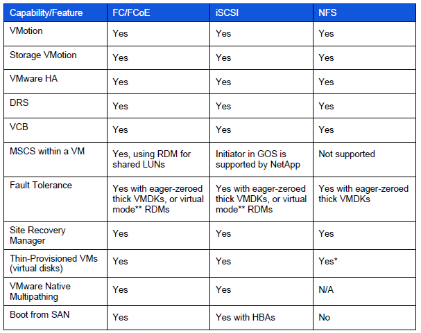
What is iSCSI Target Server?
iSCSI Target allows your Windows Server to share block storage remotely. iSCSI leverages the Ethernet network and does not require any specialized hardware. There is a brand new UI integrated with Server manager, along with 20+ cmdlets for easy management.
iSCSI Terms
- iSCSI:
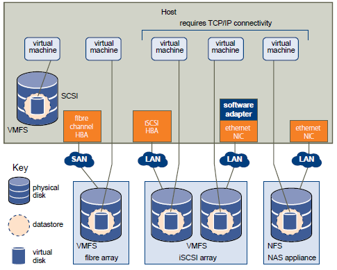
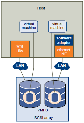
An industry standard protocol allow sharing block storage over the Ethernet. The server shares the storage is called iSCSI Target. The server (machine) consumes the storage is called iSCSI initiator. Typically, the iSCSI initiator is an application server. For example, iSCSI Target provides storage to a SQL server, the SQL server will be the iSCSI initiator in this deployment.
- Target:
It is an object which allows the iSCSI initiator to make a connection. The Target keeps track of the initiators which are allowed to be connected to it. The Target also keeps track of the iSCSI virtual disks which are associated with it. Once the initiator establishes the connection to the Target, all the iSCSI virtual disks associated with the Target will be accessible by the initiator.
- iSCSI Target Server:
The server runs the iSCSI Target. It is also the iSCSI Target role name in Windows Server 2012.
- iSCSI virtual disk:
It also referred to as iSCSI LUN. It is the object which can be mounted by the iSCSI initiator. The iSCSI virtual disk is backed by the VHD file.
- iSCSI connection:
iSCSI initiator makes a connection to the iSCSI Target by logging on to a Target. There could be multiple Targets on the iSCSI Target Server, each Target can be accessed by a defined list of initiators. Multiple initiators can make connections to the same Target. However, this type of configuration is only supported with clustering. Because when multiple initiators connects to the same Target, all the initiators can read/write to the same set of iSCSI virtual disks, if there is no clustering (or equivalent process) to govern the disk access, corruption will occur. With Clustering, only one machine is allowed to access the iSCSI virtual disk at one time.
- IQN:
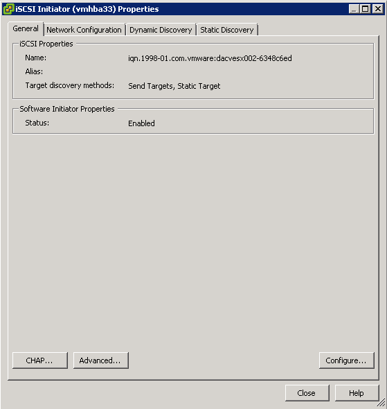
It is a unique identifier of the Target or Initiator. The Target IQN is shown when it is created on the Server. The initiator IQN can be found by typing a simple “iscsicli” cmd in the command window.
- Loopback:
There are cases where you want to run the initiator and Target on the same machine; it is referred as “loopback”. In Windows Server 2012, it is a supported configuration. In loopback configuration, you can provide the local machine name to the initiator for discovery, and it will list all the Targets which the initiator can connect to. Once connected, the iSCSI virtual disk will be presented to the local machine as a new disk mounted. There will be performance impact to the IO, since it will travel through the iSCSI initiator and Target software stack when comparing to other local I/Os. One use case of this configuration is to have initiators writing data to the iSCSI virtual disk, then mount those disks on the Target server (using loopback) to check the data in read mode.
Instructions
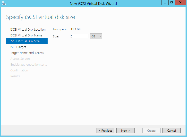
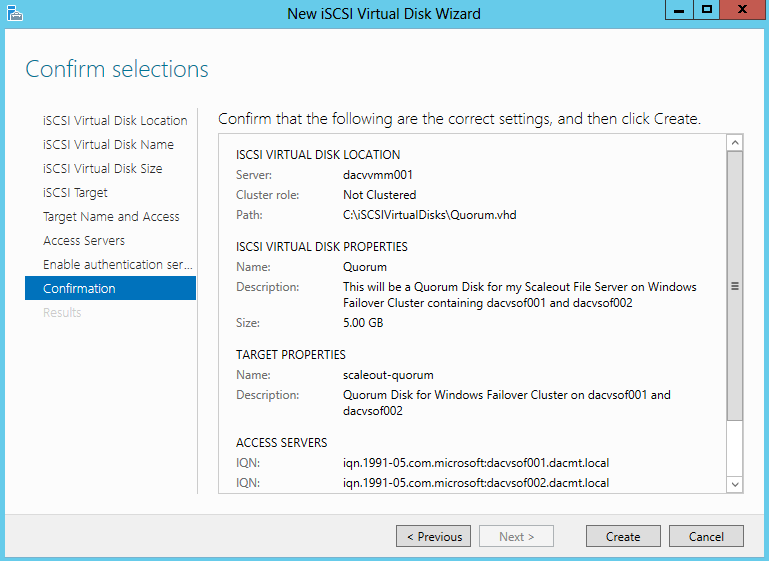
The aim of this particular blog is to configure an iSCSI Target Disk which my Windows Server 2012 Failover Cluster can use as its Quorum Disk so we will be configuring a 5GB Quorum Disk which we will then present to the Failover Cluster Servers
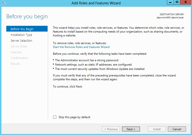
- Open Server Manager and click Add Roles and Features
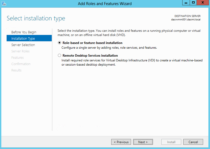
- Choose Role based or Feature based installation
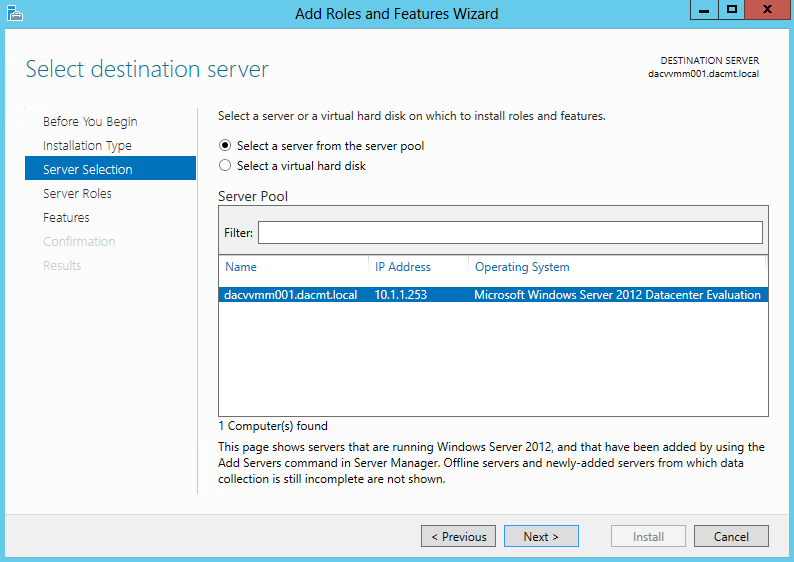
- Select Destination Server
- Select Server Roles > File and Storage Services > File and iSCSI Services > iSCSI Target Server
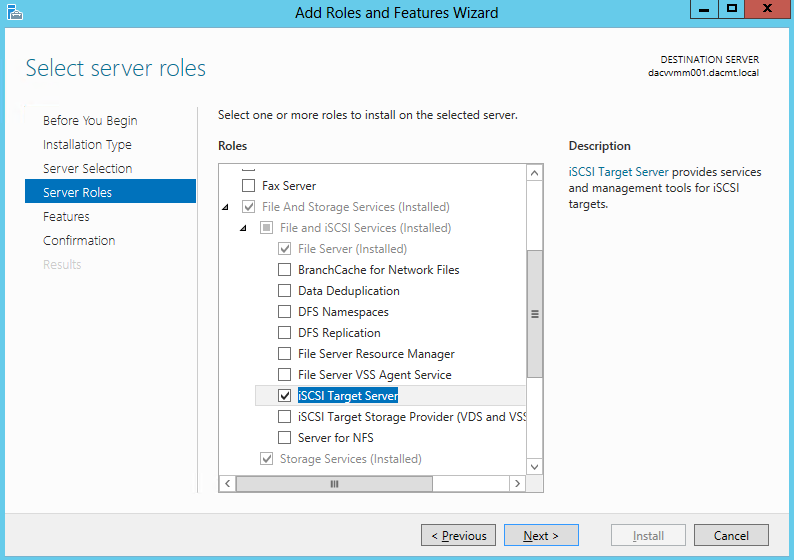
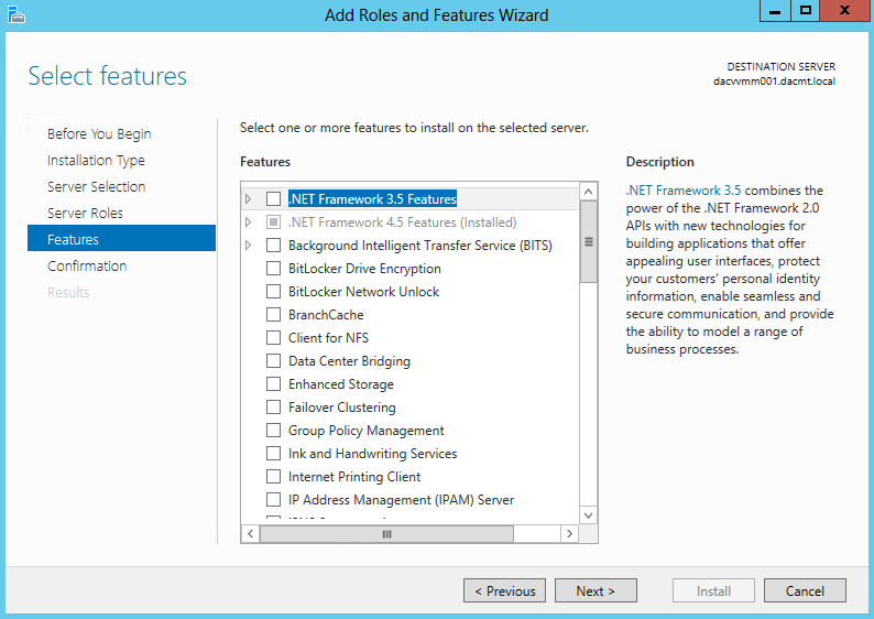
- Add Features that are required for iSCSI Target Server (None ticked here)
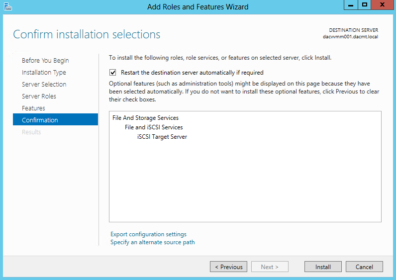
- Confirm Installation Selections
- To complete iSCSI target server the configuration go to Server Manager , click File and Storage Services > iSCSI
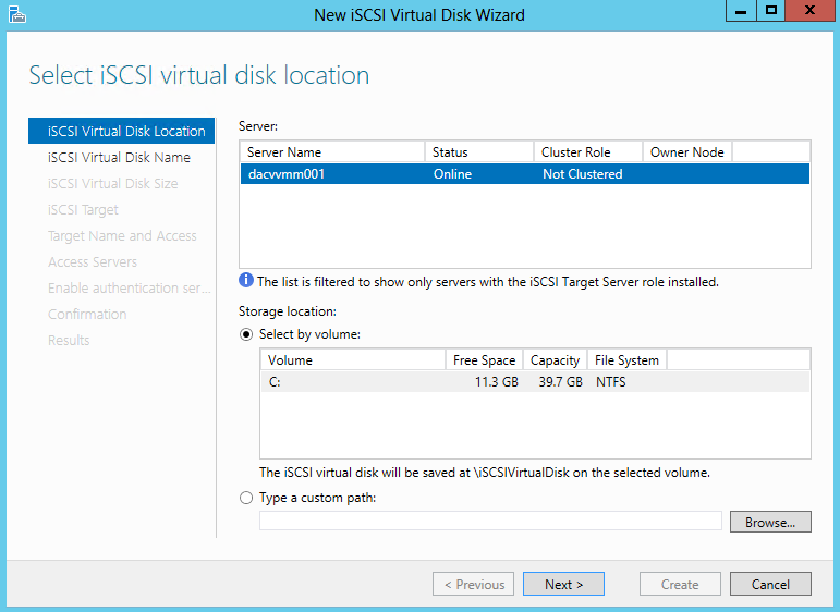
- Go to iSCSI Virtual disks and click “Launch the New Virtual Disk wizard to create a virtual disk” and walk through the Virtual Disks and targets creation
- Select an iSCSI virtual disk location
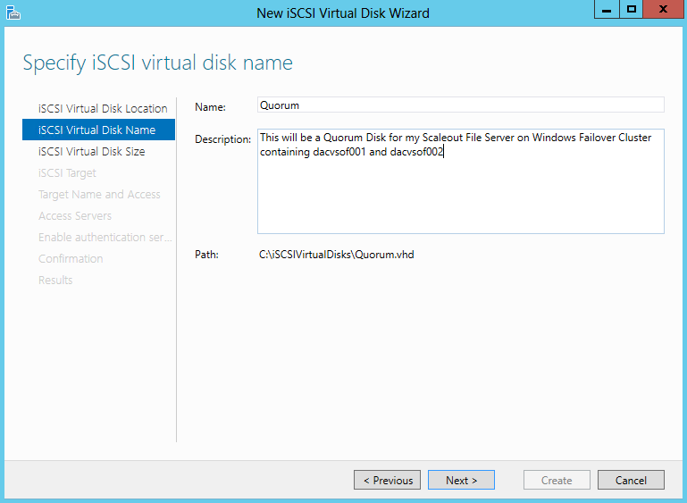
- Specify iSCSI virtual disk name
- Specify iSCSI virtual disk size
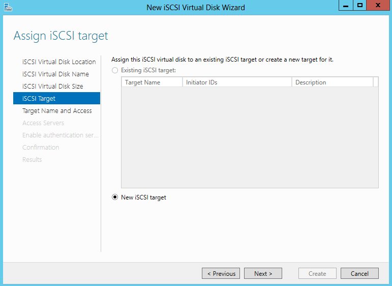
- Assign iSCSI Target
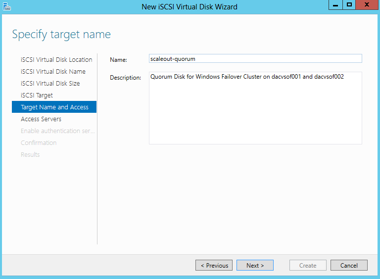
- Specify Target Name. Underscores are not allowed but it will change them for you
- Specify Access Servers
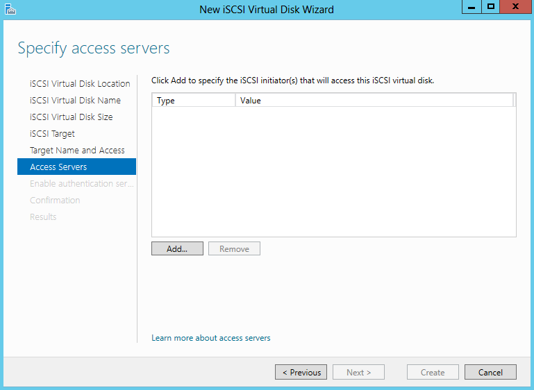
- Select a method to identify the initiator
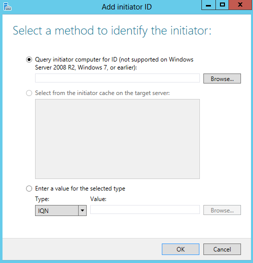
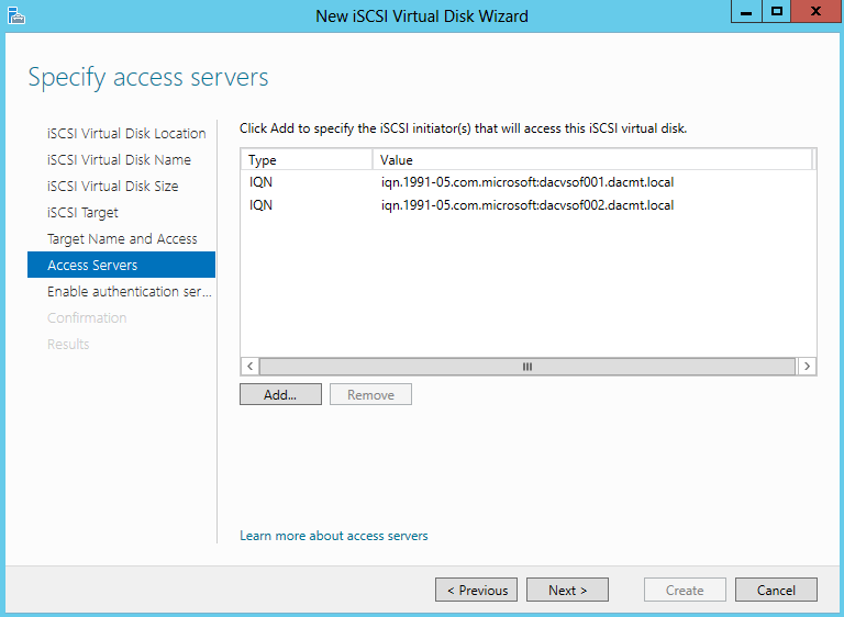
- Click Browse and type in the name of the servers which will need to access this virtual disk
- I have added my 2 Windows Failover Cluster VMs which are called dacvsof001 and dacvsof002
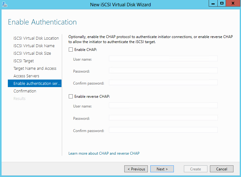
- Enable Authentication
- Confirm Selections
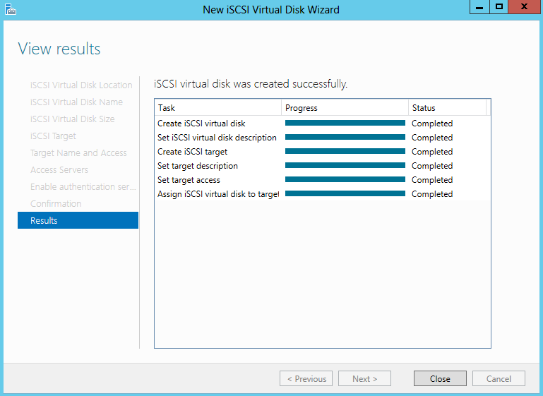
- View Results
- Next we need to go to the first Failover Cluster Server dacvsof001 and add the disk
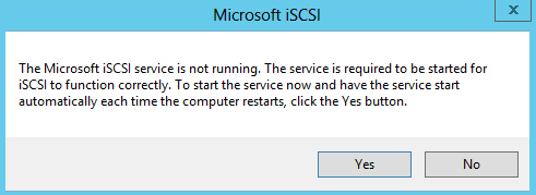
- On dacvsof001, open Server Manager click Tools and select iSCSI Initiator. When you select this, you will get the following message. Click Yes
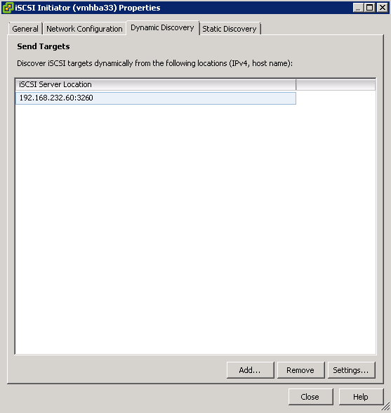
- Type the Target Server address in which is the server you created the Virtual Disk on and click Quick Connect
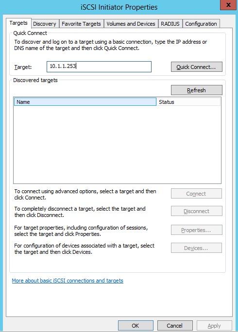
- You will the Target listed which is available for connection
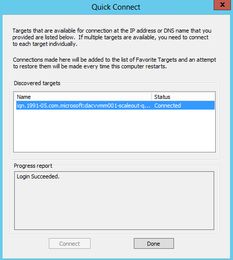
- Click Done
- Now open Disk Management to make sure that the disk is presented correctly
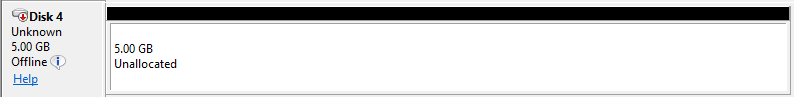
- Right click on this and select Online
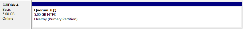
- Right click again and select Initialise
- Create new Volume. I used Q for Quorum Disk
- Now go to the second Windows Failover Cluster Server and do exactly the same thing
- Leave this disk online and initialised but not given a letter