Archive for Objective 1 Storage

Configure Software iSCSI Port Bindings

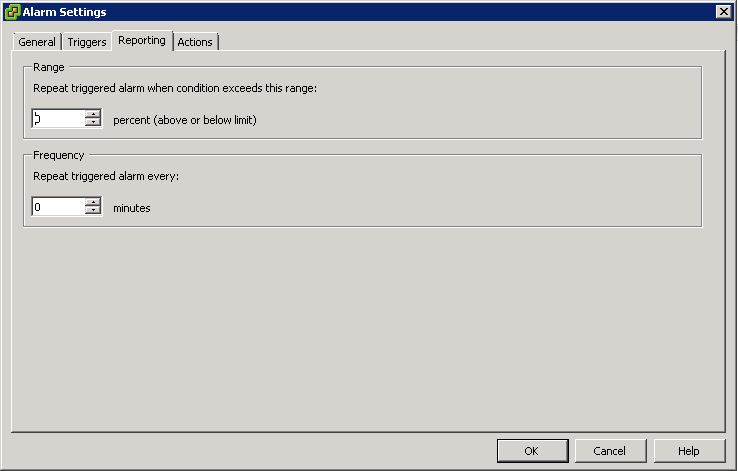
What is Software iSCSI port binding?

Software iSCSI port binding is the process of creating multiple paths between iSCSI adapters and an iSCSI Storage target. By default, ESXi does not setup multipathing for iSCSI adapters. As a result, all targets are accessible by only a single path. This is true regardless of if teaming was setup for your NICS on the VMkernel port used for iSCSI. To ensure that your storage is still accessible in the event of a path failure or to take advantage of load balancing features, Software iSCSI Port Binding is required.

Capture

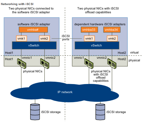
With the software-based iSCSI implementation, you can use standard NICs to connect your host to a remote iSCSI target on the IP network. The software iSCSI adapter that is built into ESXi facilitates this connection by communicating with the physical NICs through the network stack.

Before you can use the software iSCSI adapter, you must

  • Set up networking
  • Activate the adapter
  • Configure parameters such as discovery addresses and CHAP

Setup Networking

Software and dependent hardware iSCSI adapters depend on VMkernel networking. If you use the software or dependent hardware iSCSI adapeters, you must configure connections for the traffic between the iSCSI component and the physical network adapters. Configuring the network connection involves creating a virtual VMkernel interface for each physical network adapter and associating the interface with an appropriate iSCSI adapter.

If you use a single vSphere standard switch to connect VMkernel to multiple network adapters, change the port group policy, so that it is compatible with the iSCSI network requirements.

By default, for each virtual adapter on the vSphere standard switch, all network adapters appear as active. You must override this port group policy setup, so that each VMkernel interface maps to only one corresponding active NIC. For example

  • vmk1 maps to vmnic1
  • vmk2 maps to vmnic2

Procedure

  • Create a vSphere standard switch that connects VMkernel with physical network adapters designated for iSCSI traffic. The number of VMkernel adapters must correspond to the number of physical adapters on the vSphere standard switch
  • Log in to the vSphere Client and select the host from the inventory panel.
  • Click the Configuration tab and click Networking
  • Select the vSphere standard switch that you use for iSCSI and click Properties.
  • On the Ports tab, select an iSCSI VMkernel adapter and click Edit.
  • Click the NIC Teaming tab and select Override switch failover order.

iscsi

  • Designate only one physical adapter as active and move all remaining adapters to the Unused Adapters category. You will see a Warning Trianlge against your iSCSI VMKernel port if you don’t.
  • Repeat Step 4 through Step 6 for each iSCSI VMkernel interface on the vSphere standard switch.
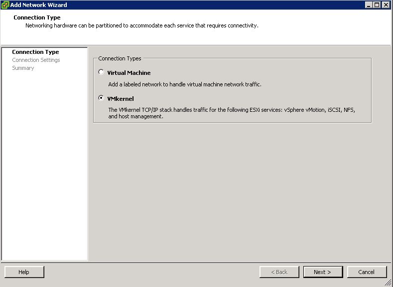
  • Next go to the switch properties and click Add and choose VMkernel

vmkernel

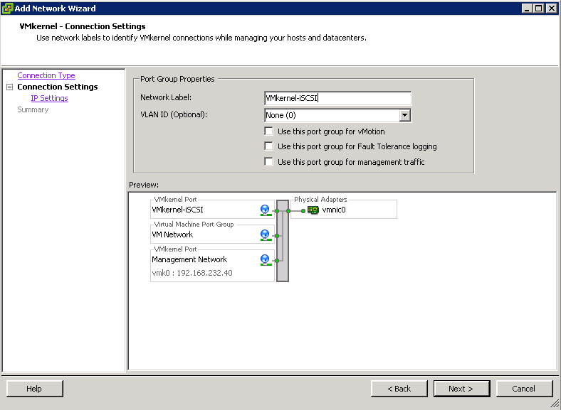
  • Type a name. Eg VMkernel-iSCSI

ISCSI1

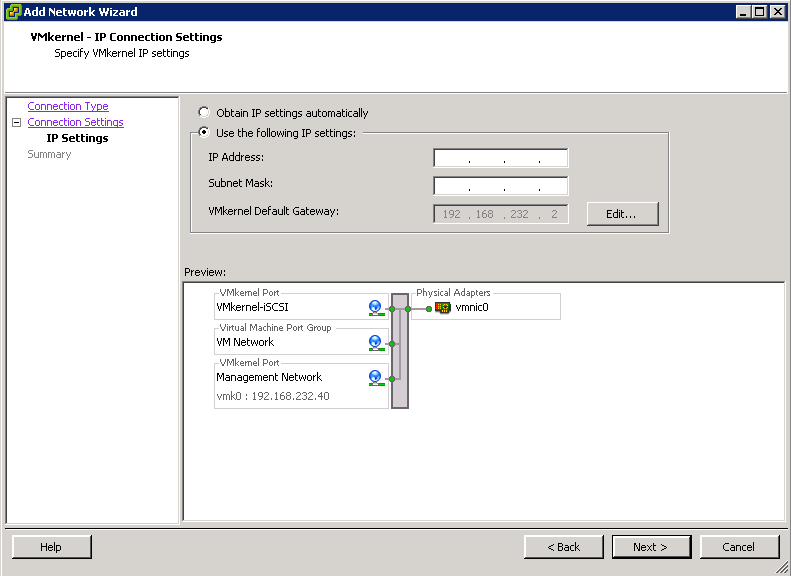
  •  Enter an IP Address for this adapter

iscsi2

  • Finish and check Summary Page

Setup Software iSCSI Adapter

  • Within the Host View, click the Configuration tab > Storage Adapters
  • Click Add to add a Software iSCSI Adapter
  • Right click the new Software iSCSI Adapter and select Properties

ISCSI3

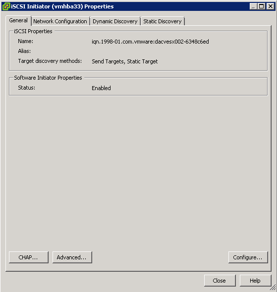
  • Enable the adapter if it is not already
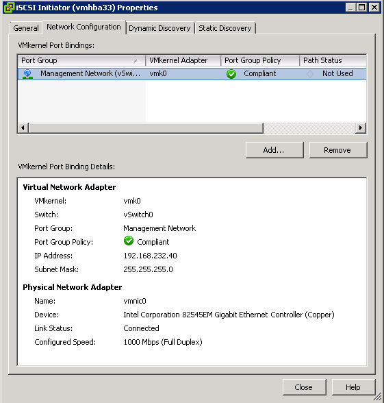
  • Open the Network Configuration tab
  • Add the new port group(s) associated with the iSCSI network

ISCSI4

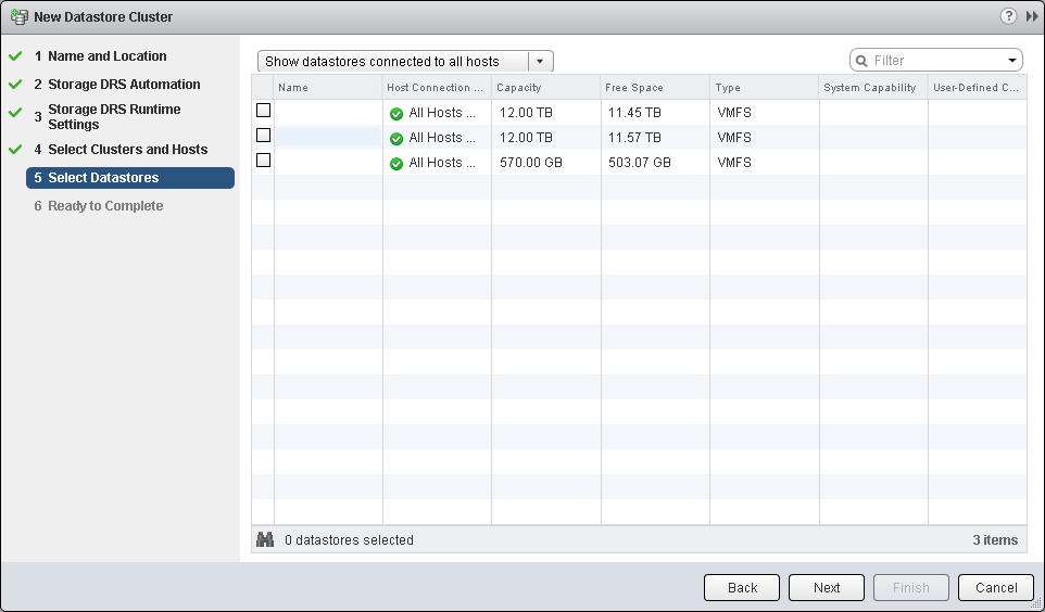
  • Click the Dynamic Discovery tab

ISCSI5

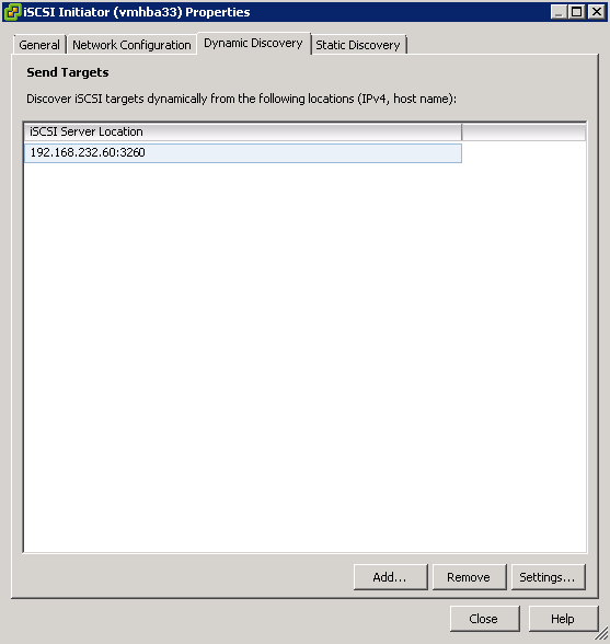
  • Add the IP addresses of the ISCSI targets
  • Click Static Discovery and check the details in here

ISCSI6

  • Click Close
  • Rescan the attached disks

What if you have multiple adapters?

  • If your host has more than one physical network adapter for software and dependent hardware iSCSI, use the adapters for multipathing.
  • You can connect the software iSCSI adapter with any physical NICs available on your host. The dependent iSCSI adapters must be connected only with their own physical NICs.
  • Physical NICs must be on the same subnet as the iSCSI storage system they connect to.

The iSCSI adapter and physical NIC connect through a virtual VMkernel adapter, also called virtual network adapter or VMkernel port. You create a VMkernel adapter (vmk) on a vSphere switch (vSwitch) using 1:1 mapping between each virtual and physical network adapter.

One way to achieve the 1:1 mapping when you have multiple NICs, is to designate a separate vSphere switch for each virtual-to-physical adapter pair. The following examples show configurations that use vSphere standard switches, but you can use distributed switches as well.

Capture1

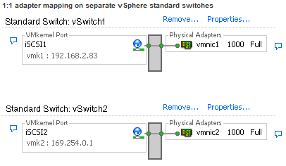
If you use separate vSphere switches, you must connect them to different IP subnets.
Otherwise, VMkernel adapters might experience connectivity problems and the host
will fail to discover iSCSI LUNs

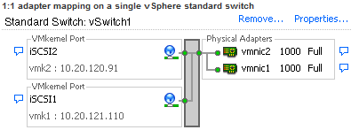
An alternative is to add all NICs and VMkernel adapters to a single vSphere
standard switch. In this case, you must override the default network setup and
make sure that each VMkernel adapter maps to only one corresponding active
physical adapter.

Capture2

General Information on iSCSI Adapters

http://www.electricmonk.org.uk/2012/04/18/using-esxi-with-iscsi-sans/

Change a Multipath Policy

policy1

Changing Path Policies

You can change path policies with

  • esxcli
  • vicfg-mpath

What Path Policies are there?

  • Most Recently Used (MRU)

Selects the first working path, discovered at system boot time. If this path becomes unavailable, the ESXi/ESX host switches to an alternative path and continues to use the new path while it is available. This is the default policy for Logical Unit Numbers (LUNs) presented from an Active/Passive array. ESXi/ESX does not return to the previous path if, or when, it returns; it remains on the working path until it, for any reason, fails.

Note: The preferred flag, while sometimes visible, is not applicable to the MRU pathing policy and can be disregarded

  • Fixed (Fixed)

Uses the designated preferred path flag, if it has been configured. Otherwise, it uses the first working path discovered at system boot time. If the ESXi/ESX host cannot use the preferred path or it becomes unavailable, the ESXi/ESX host selects an alternative available path. The host automatically returns to the previously-defined preferred path as soon as it becomes available again. This is the default policy for LUNs presented from an Active/Active storage array.

  • Round Robin (RR)

Uses an automatic path selection rotating through all available paths, enabling the distribution of load across the configured paths. For Active/Passive storage arrays, only the paths to the active controller will be used in the Round Robin policy. For Active/Active storage arrays, all paths will be used in the Round Robin policy.

Note: This policy is not currently supported for Logical Units that are part of a Microsoft Cluster Service (MSCS) virtual machine.

  • Fixed path with Array Preference

The VMW_PSP_FIXED_AP policy was introduced in ESXi/ESX 4.1. It works for both Active/Active and Active/Passive storage arrays that support Asymmetric Logical Unit Access (ALUA). This policy queries the storage array for the preferred path based on the array’s preference. If no preferred path is specified by the user, the storage array selects the preferred path based on specific criteria.

Note: The VMW_PSP_FIXED_AP policy has been removed from ESXi 5.0. For ALUA arrays in ESXi 5.0, the MRU Path Selection Policy (PSP) is normally selected but some storage arrays need to use Fixed. To check which PSP is recommended for your storage array, see the Storage/SAN section in the VMware Compatibility Guide or contact your storage vendor.

Notes:

  • These pathing policies apply to VMware’s Native Multipathing (NMP) Path Selection Plug-ins (PSP). Third-party PSPs have their own restrictions.
  • Round Robin is not supported on all storage arrays. Please check with your array documentation or storage vendor to verify that Round Robin is supported and/or recommended for your array and configuration. Switching to a unsupported or undesirable pathing policy can result in connectivity issues to the LUNs (in a worst-case scenario, this can cause an outage).

Changing Path Policies with ESXCLI

  • Ensure your device is claimed by the NMP plugin. Only NMP devices allow you to change the path policy.
  • esxcli storage nmp device list

Multipath1

  • Retrieve the list of path selection policies on the system to see which values are valid for the –psp option when you set the path policy.
  • esxcli storage core plugin registration list

multipath2

  • Set the path policy using esxcli.
  • esxcli storage nmp device set - -device naa.xxx - -psp VMW_PSP_RR

MULTIPATH3

(Optional) If you specified the VMW_PSP_FIXED policy, you must make sure the preferred path is set correctly.

  • Check which path is the preferred path for a device.
  • esxcli storage nmp psp fixed deviceconfig get - -device naa.xxx b  If necessary, change the preferred path.
  • Set the preferred path to vmhba32:C0:T0:L0
  • esxcli storage nmp psp fixed deviceconfig set - -device naa.xxx –path vmhba32:C0:T0:L0

multipath4

  • Run the command with –default to clear the preferred path selection.

Perform command line configuration of multipathing options

signpost

Multipathing Considerations

Specific considerations apply when you manage storage multipathing plug-ins and claim rules. The following considerations help you with multipathing

  • If no SATP is assigned to the device by the claim rules, the default SATP for iSCSI or FC devices is VMW_SATP_DEFAULT_AA. The default PSP is VMW_PSP_FIXED.
  • When the system searches the SATP rules to locate a SATP for a given device, it searches the driver rules first. If there is no match, the vendor/model rules are searched, and finally the transport rules are searched. If no match occurs, NMP selects a default SATP for the device.
  • If VMW_SATP_ALUA is assigned to a specific storage device, but the device is not ALUA-aware, no claim rule match occurs for this device. The device is claimed by the default SATP based on the device’s transport type.
  • The default PSP for all devices claimed by VMW_SATP_ALUA is VMW_PSP_MRU. The VMW_PSP_MRU selects an active/optimized path as reported by the VMW_SATP_ALUA, or an active/unoptimized path if there is no active/optimized path. This path is used until a better path is available (MRU). For example, if the VMW_PSP_MRU is currently using an active/unoptimized path and an active/optimized path becomes available, the VMW_PSP_MRU will switch the current path to the active/optimized one.
  • If you enable VMW_PSP_FIXED with VMW_SATP_ALUA, the host initially makes an arbitrary selection of the preferred path, regardless of whether the ALUA state is reported as optimized or unoptimized. As a result, VMware does not recommend to enable VMW_PSP_FIXED when VMW_SATP_ALUA is used for an ALUA-compliant storage array. The exception is when you assign the preferred path to be to one of the redundant storage processor (SP) nodes within an active-active storage array. The ALUA state is irrelevant.
  • By default, the PSA claim rule 101 masks Dell array pseudo devices. Do not delete this rule, unless you want to unmask these devices.

What can we use to configure Multipath Options

  • vCLI
  • vMA
  • Putty into DCUI console

What we can view and adjust

  • You can display all multipathing plugins available on your host
  • You can list any 3rd Party MPPs as well as your hosts PSP and SATPs and review the paths they claim
  • You can also define new paths and specify which multipathing plugin should claim the path

The ESXCLI Commands

Click the link to take you to the vSphere 5 Documentation Center for each command

These are the 2 commands you need to use to perform configuration of multipathing

nmp

nmp2

esxcli storage nmp psp Namespaces

generic1

Display NMP PSPs

  • esxcli storage nmp psp list

This command list all the PSPs controlled by the VMware NMP

psplist

More complicated commands with esxcli storage nmp psp namespace

  • esxcli storage nmp psp fixed deviceconfig set - -device naa.xxx –path vmhba3:C0:T5:L3

The command sets the preferred path to vmhba3:C0:T5:L3. Run the command with – -default to clear the preferred path selection

esxcli storage nmp satp Namespaces

generic2

Display SATPs for the Host

  • esxcli storage nmp satp list

For each SATP, the output displays information that shows the type of storage array or system this SATP supports and the default PSP for any LUNs using this SATP. Placeholder (plugin not loaded) in the Description column indicates that the SATP is not loaded.

satplist

More complicated commands with esxcli storage nmp satp namespaces

  • esxcli storage nmp satp rule add -V NewVend -M NewMod -s VMW_SATP_INV

The command assigns the VMW_SATP_INV plug-in to manage storage arrays with vendor string NewVend and model string NewMod.

esxcli storage nmp device NameSpaces

generic3

Display NMP Storage Devices

  • esxcli storage nmp device list

This command list all storage devices controlled by the VMware NMP and displays SATP and PSP information associated with each device

devicelist

More complicated commands with esxcli storage nmp device namespaces

  • esxcli storage nmp device set - -device naa.xxx - -psp VMW_PSP_FIXED

This command sets the path policy for the specified device to  VMW_PSP_FIXED

esxcli storage nmp path Namespaces

generic4

Display NMP Paths

  • esxcli storage nmp path list

This command list all the paths controlled by the VMware NMP and displays SATP and PSP information associated with each device

pathlist

More complicated commands with esxcli storage nmp path namespaces

There is only really the list command associated with this command

esxcli storage core Command Namespaces

storagecore

esxcli storage core adapter Command Namespaces

storagecore2

esxcli storage core device Command Namespaces

core3

esxcli storage core path Command Namespaces

core4

esxcli storage core plugin Command Namespaces

core5

esxcli storage core claiming Command Namespaces

core6

The esxcli storage core claiming namespace includes a number of troubleshooting commands. These  commands are not persistent and are useful only to developers who are writing PSA plugins or troubleshooting a system. If I/O is active on the path, unclaim  and reclaim actions fail

The help for esxcli storage core claiming includes the autoclaim command. Do not use this command unless instructed to do so by VMware support staff

esxcli storage core claimrule Command Namespaces

core7

The PSA uses claim rules to determine which multipathing module should claim the paths to a particular device and to manage the device. esxcli storage core claimrule manages claim rules.

Claim rule modification commands do not operate on the VMkernel directly. Instead they operate on the configuration file by adding and removing rules

To change the current claim rules in the VMkernel
1
Run one or more of the esxcli storage core claimrule modification commands (add, remove, or move).
2
Run esxcli storage core claimrule load to replace the current rules in the VMkernel with the modified rules from the configuration file.

Claim rules are numbered as follows.

  • Rules 0–100 are reserved for internal use by VMware.
  • Rules 101–65435 are available for general use. Any third party multipathing plugins installed on your system use claim rules in this range. By default, the PSA claim rule 101 masks Dell array pseudo devices. Do not remove this rule, unless you want to unmask these devices.
  • Rules 65436–65535 are reserved for internal use by VMware.

When claiming a path, the PSA runs through the rules starting from the lowest number and determines is a path matches the claim rule specification. If the PSA finds a match, it gives the path to the corresponding plugin. This is worth noticing because a given path might match several claim rules.

The following examples illustrate adding claim rules.  

  • Add rule 321, which claims the path on adapter vmhba0, channel 0, target 0, LUN 0 for the NMP plugin.
  • esxcli storage core claimrule add -r 321 -t location -A vmhba0 -C 0 -T 0 -L 0 -P NMP
  • Add rule 429, which claims all paths provided by an adapter with the mptscsi driver for the MASK_PATH plugin.
  • esxcli storage core claimrule add -r 429 -t driver -D mptscsi -P MASK_PATH
  • Add rule 914, which claims all paths with vendor string VMWARE and model string Virtual for the NMP plugin.
  • esxcli storage core claimrule add -r 914 -t vendor -V VMWARE -M Virtual -P NMP
  • Add rule 1015, which claims all paths provided by FC adapters for the NMP plugin.
  • esxcli storage core claimrule add -r 1015 -t transport -R fc -P NMP

Example: Masking a LUN

In this example, you mask the LUN 20 on targets T1 and T2 accessed through storage adapters vmhba2 and vmhba3.

  • esxcli storage core claimrule list
  • esxcli  storage core claimrule add -P MASK_PATH -r 109 -t location -A
    vmhba2 -C 0 -T 1 -L 20
  • esxcli storage core claimrule add -P MASK_PATH -r 110 -t location -A
    vmhba3 -C 0 -T 1 -L 20
  • esxcli  storage core claimrule add -P MASK_PATH -r 111 -t location -A
    vmhba2 -C 0 -T 2 -L 20
  • esxcli storage core claimrule add -P MASK_PATH -r 112 -t location -A
    vmhba3 -C 0 -T 2 -L 20
  • esxcli storage core claimrule load
  • esxcli storage core claimrule list
  • esxcli storage core claiming unclaim -t location -A vmhba2
  • esxcli storage core claiming unclaim -t location -A vmhba3
  • esxcli storage core claimrule run

Install and Configure PSA Plugins

scales

Methods of Installing PSA Plugins

  • Using vCenter Update Manager
  • Using vCLI (use the esxcli software vib install command)
  • Using Vendor recommended Installation Guides
  • Using EMC’s Powerpath Installer
  • Using Dell’s Equalogic setup.pl script for their multipathing extension module
  • Using vihostupdate –server esxihost –install –bundle=Powerpath.5.4.SP2.zip

Checking Registration and Adding a Plugin

  • esxcli storage core plugin registration list will check if it is registered
  • esxcli storage core plugin registration add -m class_satp_va -N SATP -P class_satp_VA
  • Reboot the host(s) in order for the new PSP to take effect

Changing the VMW_SATP_CX# default PSP from VMW_PSP_MRU to VMW_PSP_RR

  • esxcli storage nmp satp set -s VMW_SATP_CX -P VMW_PSP_RR
  • Reboot the host(s) in order for the new PSP to take effect

VMware Document

vSphere Command-Line Interface Concepts and Examples ESXi 5.0

Understanding different multipathing Policy Functionalities

images

Types of Multipathing explained

  • VMW_PSP_FIXED
  • The host uses the designated preferred path, if it has been configured. Otherwise, the host selects the first working path discovered at system boot time.
  • If you want the host to use a particular preferred path, specify it through the vSphere Client or by using esxcli storage nmp psp fixed deviceconfig set.
  • The default policy for active‐active storage devices is VMW_PSP_FIXED however VMware does not recommend you use VMW_PSP_FIXED for devices that have the VMW_SATP_ALUA storage array type policy assigned to them.
  • Fixed is the default policy for most active-active storage devices.
  • If the host uses a default preferred path and the path’s status turns to Dead, a new path is selected as preferred. However, if you explicitly designate the preferred path, it will remain preferred even when it becomes inaccessible
  • VMW_PSP_MRU
  • The host selects the path that it used most recently.
  • When the path becomes unavailable, the host selects an alternative path. The host does not revert back to the original path when that path becomes available again.
  • There is no preferred path setting with the MRU policy.
  • MRU is the default policy for active‐passive storage devices.
  • VMW_PSP_RR
  • The host uses an automatic path selection algorithm that rotates through all active paths when connecting to active‐passive arrays, or through all available paths when connecting to active‐active arrays.
  • Automatic path selection implements load balancing across the physical paths available to your host.
  • Load balancing is the process of spreading I/O requests across the paths. The goal is to optimize throughput performance such as I/O per second, megabytes per second, or response times.
  • VMW_PSP_RR is the default for a number of arrays and can be used with both active‐active and active‐passive arrays to implement load balancing across paths for different LUNs.

View Datastore Paths

Use the vSphere Client to review the paths that connect to storage devices the datastores are deployed on.

  • Log in to the vSphere Client and select a host from the inventory panel.
  • Click the Configuration tab and click Storage in the Hardware panel.
  • Click Datastores under View.
  • From the list of configured datastores, select the datastore whose paths you want to view, and click Properties.
  • Under Extents, select the storage device whose paths you want to view and click Manage Paths.
  • In the Paths panel, select the path to view
  • The panel underneath displays the path’s name. The name includes parameters describing the path:adapter ID, target ID, and device ID.
  • (Optional) To extract the path’s parameters, right-click the path and select Copy path to clipboard.

View Storage Device Paths

Use the vSphere Client to view which SATP and PSP the host uses for a specific storage device and the status of all available paths for this storage device.

  • Log in to the vSphere Client and select a server from the inventory panel.
  • Click the Configuration tab and click Storage in the Hardware panel.
  • Click Devices under View.
  • Select the storage device whose paths you want to view and click Manage Paths.
  • In the Paths panel, select the path to view
  • The panel underneath displays the path’s name. The name includes parameters describing the path:adapter ID, target ID, and device ID.
  • (Optional) To extract the path’s parameters, right-click the path and select Copy path to clipboard.

vifs for Command Line

230px-Diesel_engine_(PSF)

What is vifs?

vifs allows you to perform file system operations on remote hosts. The command is supported against ESXi hosts but not against vCenter Server systems.

The vifs command performs common operations such as copy, remove, get, and put on files and directories. The command is supported against ESX/ESXi hosts but not against vCenter Server systems.

Note: While there are some similarities between vifs and DOS or Unix file system management utilities, there are also many differences. For example, vifs does not support wildcard characters or current directories and, as a result, relative path names. Use vifs only as documented.

Note: To use vifs, you will need vCLI installed on  either a Windows/Linux system or you may use VMware vMA

Options using vCLI

vifs

Examples

Note: On Windows, the extension .pl is required for vicfg- commands, but not for ESXCLI.

The following examples assume you are specifying connection options, either explicitly or, for example, by specifying the server, user name, and password. Run vifs –help or vifs.pl –help for a list of common options including connection options.

  • Copy a file to another location:

vifs – -server server01 -c “[StorageName] VM/VM.vmx” “[StorageName] VM_backup/VM.vmx”

  • List all the datastores:

vifs – -server server01 -S

  • List all the directories:

vifs – -server server01 -D “[StorageName] vm”

  • Upload a file to the remote datastore:

vifs – -server server01 -p “tmp/backup/VM.pl”
“[StorageName] VM/VM.txt” -Z “ha-datacenter”

  • Delete a file:

vifs – -server server01 -r “[StorageName] VM/VM.txt” -Z “ha-datacenter”

  • List the paths to all datacenters available in the server:

vifs – -server server01 -C

  • Download a file on the host to a local path:

vifs – -server server01 -g  “[StorageName] VM/VM.txt”
-Z “ha-datacenter” “tmp/backup/VM.txt”

  • Move a file to another location:

vifs – -server server01 -m  “[StorageName] VM/VM.vmx”
“[StorageName] vm/vm_backup.vmx” -Z “ha-datacenter”

  • Remove an existing directory:

vifs – -server server01 -R “[StorageName] VM/VM” -Z “ha-datacenter””

Note:

The vifs utility, in addition to providing datastore file management also provides an interface for manipulating files residing on a vSphere host. These interfaces are exposed as URLs:

  • https://esxi-host/host
  • https://esxi-host/folder
  • https://esxi-host/tmp

VMware Link

http://blogs.vmware.com/vsphere/2012/06/using-vclis-vifs-for-more-than-just-datastore-file-management.html

Configure Datastore Clusters

What is a Datastore Cluster?

A Datastore Cluster is a collection of Datastores with shared resources and a shared management interface. When you create a Datastore cluster, you can use Storage DRS to manage storage resources and balance

  • Capacity
  • Latency

General Rules

  • Datastores from different arrays can be added to the same cluster but LUNs from arrays of different types can adversely affect performance if they are not equally performing LUNs.
  • Datastore clusters must contain similar or interchangeable Datastores
  • Datastore clusters can only have ESXi 5 hosts attached
  • Do not mix NFS and VMFS datastores in the same Datastore Cluster
  • You can mix VMFS-3 and VMFS-5 Datastores in the same Datastore Cluster
  • Datastore Clusters can only be created from the vSphere client, not the Web Client
  • A VM can have its virtual disks on different Datastores

Storage DRS

Storage DRS provides initial placement and ongoing balancing recommendations assisting vSphere administrators to make placement decisions based on space and I/O capacity. During the provisioning of a virtual machine, a Datastore Cluster can be selected as the target destination for this virtual machine or virtual disk after which a recommendation for initial placement is made based on space and I/O capacity. Initial placement in a manual provisioning process has proven to be very complex in most environments and as such crucial provisioning factors like current space utilization or I/O load are often ignored. Storage DRS ensures initial placement recommendations are made in accordance with space constraints and with respect to the goals of space and I/O load balancing. These goals aim to minimize the risk of storage I/O bottlenecks and minimize performance impact on virtual machines.

Ongoing balancing recommendations are made when

  • One or more Datastores in a Datastore cluster exceeds the user-configurable space utilization which is checked every 5 minutes
  • One or more Datastores in a Datastore cluster exceeds the user-configurable I/O latency thresholds which is checked every 8 Hours
  • I/O load is evaluated by default every 8 hours. When the configured maximum space utilization or the I/O latency threshold (15ms by default) is exceeded Storage DRS will calculate all possible moves to balance the load accordingly while considering the cost and the benefit of the migration.

Storage DRS utilizes vCenter Server’s Datastore utilization reporting mechanism to make recommendations whenever the configured utilized space threshold is exceeded.

Affinity Rules and Maintenance Mode

Storage DRS affinity rules enable controlling which virtual disks should or should not be placed on the same datastore within a datastore cluster. By default, a virtual machine’s virtual disks are kept together on the same datastore. Storage DRS offers three types of affinity rules:

  1. VMDK Anti-Affinity
    Virtual disks of a virtual machine with multiple virtual disks are placed on different datastores
  2. VMDK Affinity
    Virtual disks are kept together on the same datastore
  3. VM Anti-Affinity
    Two specified virtual machines, including associated disks, are place on different datastores

In addition, Storage DRS offers Datastore Maintenance Mode, which automatically evacuates all virtual machines and virtual disk drives from the selected datastore to the remaining datastores in the datastore cluster.

Configuring Datastore Clusters on the vSphere Web Client

  • Log into your vSphere client and click on the Datastores and Datastore Clusters view
  • Right-click on your Datacenter object and select New Datastore Cluster

figure1

  • Enter in a name for the Datastore Cluster and choose whether or not to enable Storage DRS

figure2

  • Click Next
  • You can now choose whether you want a “Fully Automated” cluster that migrates files on the fly in order to optimize the Datastore cluster’s performance and utilization, or, if you prefer, you can select No Automation to approve recommendations.

figure3

  • Here you can decide what utilization levels or I/O Latency will trigger SDRS action. To benefit from I/O metric, all your hosts that will be using this datastore cluster must be version 5.0 or later. Here you can also access some advanced and very important settings like defining what is considered a marginal benefit for migration, how often does SDRS check for imbalance and how aggressive should the algorithm be

figure4

  • I/O Latency only applicable if Enable I/O metric for SDRS recommendations is ticked
  • Next you pick what standalone hosts and/or host clusters will have access to the new Datastore Cluster

figure5

  • Select from the list of datastores that can be included in the cluster. You can list datastores that are connected to all hosts, some hosts or all datastores that are connected to any of the hosts and/or clusters you have chosen in the previous step.

figure6

  • At this point check all your selections

figure7

  • Click Finish

vSphere Client Procedure

  • Right click the Datacenter and select New Datastore Cluster
  • Put in a name

cluster1

  • Click Next and select the level of automation you want

cluster2

  • Click Next and choose your sDRS Runtime Rules

cluster3

  • Click Next and select Hosts and Clusters

cluster4

  • Click Next and select your Datastores

cluster5

  • Review your settings

cluster6

  • Click Finish
  • Check the Datastores view

cluster7

Understand interactions between virtual storage provisioning and physical storage provisioning

handshake

Key Points

All these points have been covered in other blog posts before so these are just pointers. Please search for further information on this blog

  • RDM in Physical Mode
  • RDM in Virtual Mode
  • Normal Virtual Disk (Non RDM)
  • Type of Virtual hardware. E.g Paravirtual/Non Paravirtual
  • VMware vStorage APIs for Array Integration (VAAI)
  • Three virtual disk modes: Independent persistent, Independent nonpersistent, and Snapshot
  • Types of Disk (Thin, Thick, Eager Zeroed)
  • Partition alignment
  • Consider Disk queues, HBA queues, LUN queues
  • Consider hardware redundancy. E.g Multiple vkernel ports corresponding to iSCSI
  • Storage I/O Control
  • SAN Multipathing
  • Host power management settings: Some of the power management features in newer server hardware can increase storage latency

Provision and manage storage resources according to Virtual Machine requirements

Checklist1

Provision and Manage VM Storage Resources

I am going to bullet point most of this as some of it has been covered before

  • Vendor recommendations need to be taken into account
  • Type of storage. E.g FC, iSCSI, NFS etc
  • VM Swap file placement
  • What RAID storage
  • Use Tiered storage to separate High Performance VMs from Lower performing VMs
  • Choose Virtual Disk formats as required. Eager Zeroed, Thick and Thin etc
  • Initial size of disk + growth + swap file
  • VM Virtual Hardware. E.g SCSI Controllers
  • Types of disk. E.g Virtual Disk or RDM
  • NPIV requirements
  • Make sure you adhere to the vSphere Configuation maximums
  • Is replication required
  • Make sure you have a good idea of how much I/O will be generated
  • Disk alignment will be required for certain O/S’s
  • Are snapshots required
  • Will the VM be fault tolerant

Configure Datastore alarms

Configure Datastore alarms

There are five pre-configured datastore alarms that ship with vSphere 5

datastorealarms

To create a Datastore alarm

  • Right click on the vCenter icon in the vClient and select Alarm > Add Alarm
  • Click the Drop Down on Alarm Type and Select Datastores
  • You have 2 choices to monitor – Select your preference
  • Monitor for specific conditions or state, for example, CPU usgae, power state
  • Monitor for specific events occurring on this object, for example, VM powered on
  • Tick Enable this alarm

data1

  • Click Triggers
  • Click Add
  • Under Trigger Type, you can see several triggers associated with this alarm
  • Choose Datastore Disk Usage

data2

  • Click the Drop Down on Condition and select Is above or Is below
  • Click the Drop Down on Warning and select 75% or change as required
  • Click the Drop Down on Condition length and set as required. Sometimes it will not let you set this if it is not relevant
  • Click the Drop Down on Warning and select 90% or change as required
  • At the bottom of the screen there are 2 options. Choose the one you require
  • Trigger if any of the conditions are satisfied
  • Trigger if all of the conditions are satisfied
  • Click the Reporting tab
  • Under Range there is an option Repeat triggered alarm when the condition exceeds this range

A 0 value triggers and clears the alarm at the threshold point you configured. A non-zero value triggers the alarm only after the condition reaches an additional percentage above or below the threshold point.
Condition threshold + Reporting Tolerance = trigger alarmTolerance values ensure you do not transition alarm states based on false changes in a condition

  • Under Frequency there is an option Repeat triggered alarms every

The frequency sets the time period during which a triggered alarm is not reported again. When the time period has elapsed, the alarm will report again if the condition or state is still true

data3

  • Click the Actions tab
  • Click Add
  • Click the Drop Down box on Action and Select Send a notification email

data4

  • If you chose Send a notification email or Send a notification trap as the alarm action, make sure the notification settings are configured for vCenter Server
  • Double click Configuration and enter an email address
  • In the next boxes are the alarm status triggers. Set a frequency for sending an email each time the triggers occur

data5

Click OK to Finish