Installing vRA certificates
This subject is a tricky one to navigate round so I have decided to try and simplify this as much as possible to get a good working procedure to carry out the replacement of certificates correctly and efficiently. The various components of VMware vRealize Automation (formerly known as VMware vCloud Automation Center) have different requirements for the certificates used for authentication
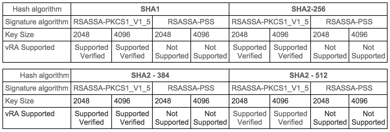
Certificates supportability matrix for vRealize Automation
Certificate trust requirements between VMware vRealize Automation components
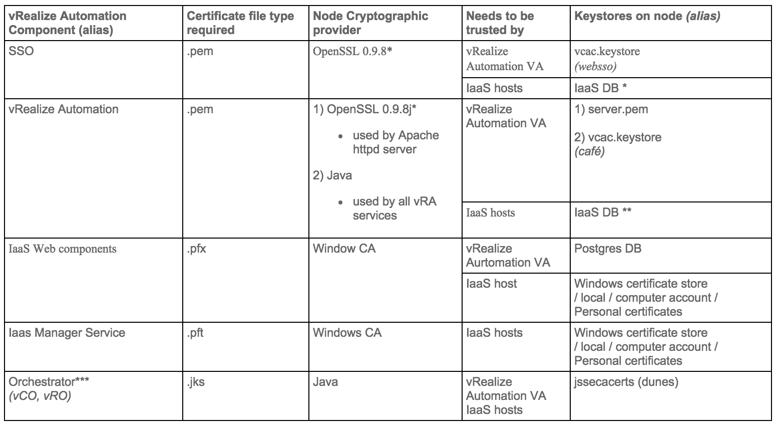
- * vRealize certificate thumbprint is stored in IaaS database during installation
- ** SSO certificate thumbprint is stored in IaaS database during installation
- *** Application Director and Orchestrator as an external instance are optional services
Update components Certificates in the following order
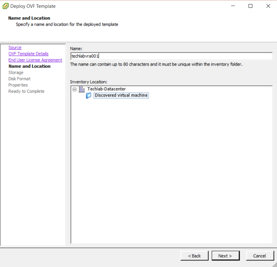
- Identity Appliance
- vCloud Automtation vCenter Appliance
- IaaS components
Step 1 Installing a Domain Certificate Authority
Note: This will normally be installed on a Domain Controller.
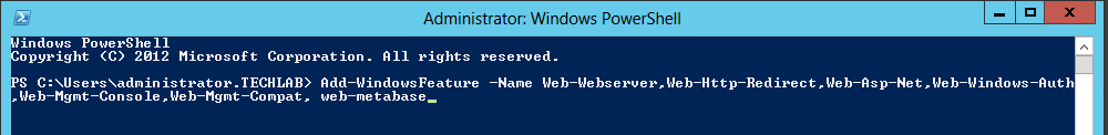
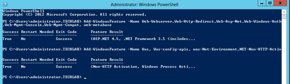
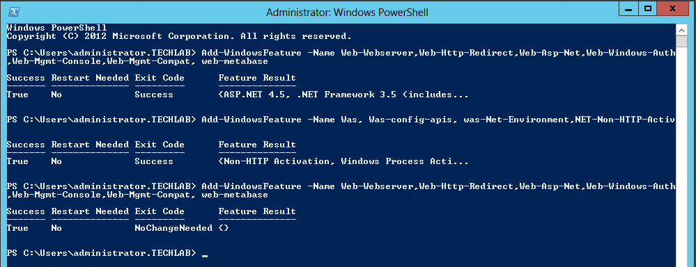
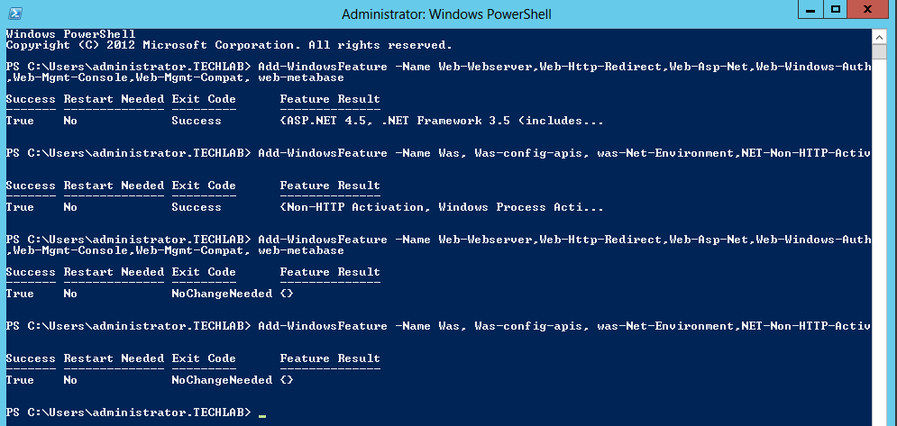
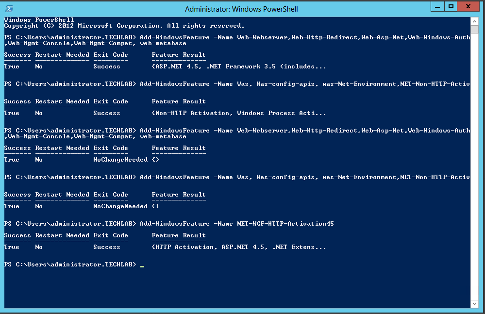
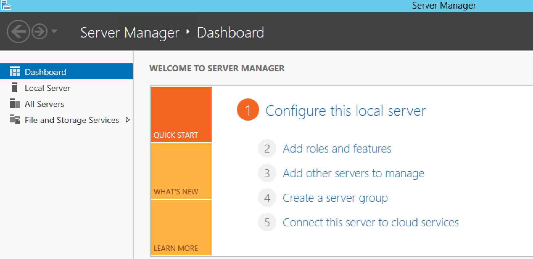
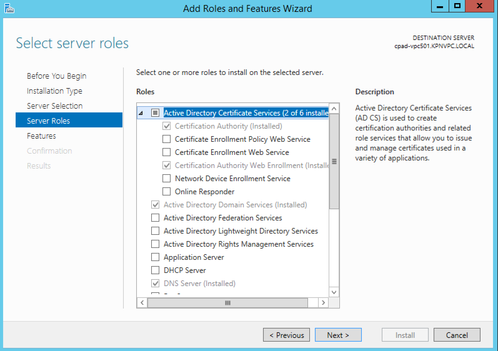
- On Windows 2012 open Server Manager > Add Roles and Features
- Click Next to accept the selections on the next 2 screens
- Make sure to choose both Certification Authority & Certifications Authority Web Enrollment on the Role Service screen
- Choose Enterprise or Subordinate at the setup Type page (Note I am choosing Enterprise and this is in my lab)
- Assuming this is your first CA, choose Root CA at the CA Type screen
- Create a new private key
- In Configure cryptography for CA, choose Microsoft Software Key Storage Provider and SHA1
- Configure your CA name
- Set validity period for the certificate generated by this CA
Step 2 Creating vCAC Certificate templates
We now need to create a non-standard Certificate Template, which is a copy of the standard Web Server template modified to allow for export of the certificate key. In addition, the Microsoft CA will be updated to allow for Subject Alternative Names (SANs) as specified in the Attributes.
- Connect to the Root CA server or Subordinate CA server via RDP.
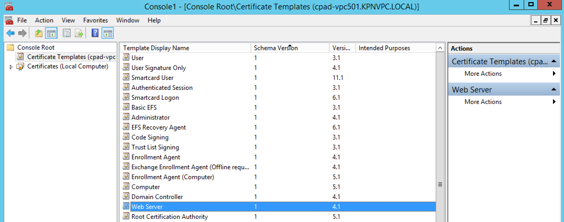
- Click Start > Run, type certtmpl.msc, and click OK. The Certificate Template Console opens.
- In the middle pane, under Template Display Name, locate Web Server.
- Right-click Web Server and click Duplicate Template.
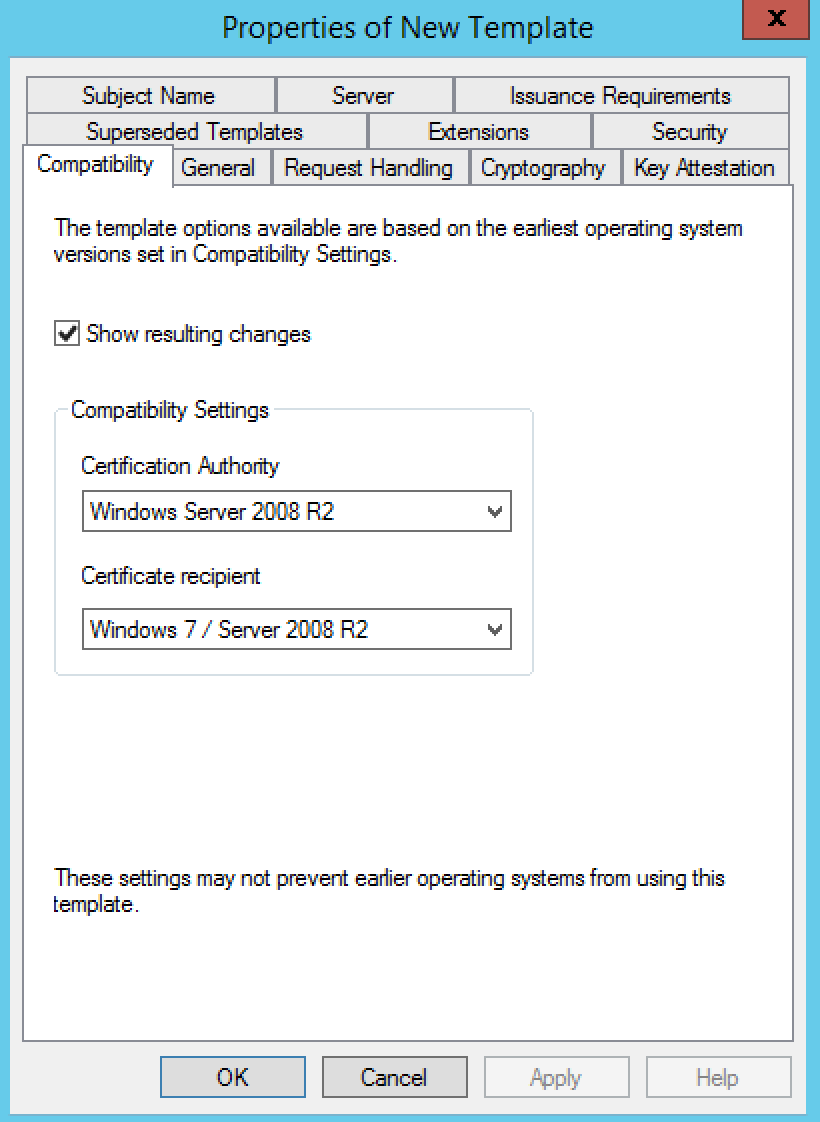
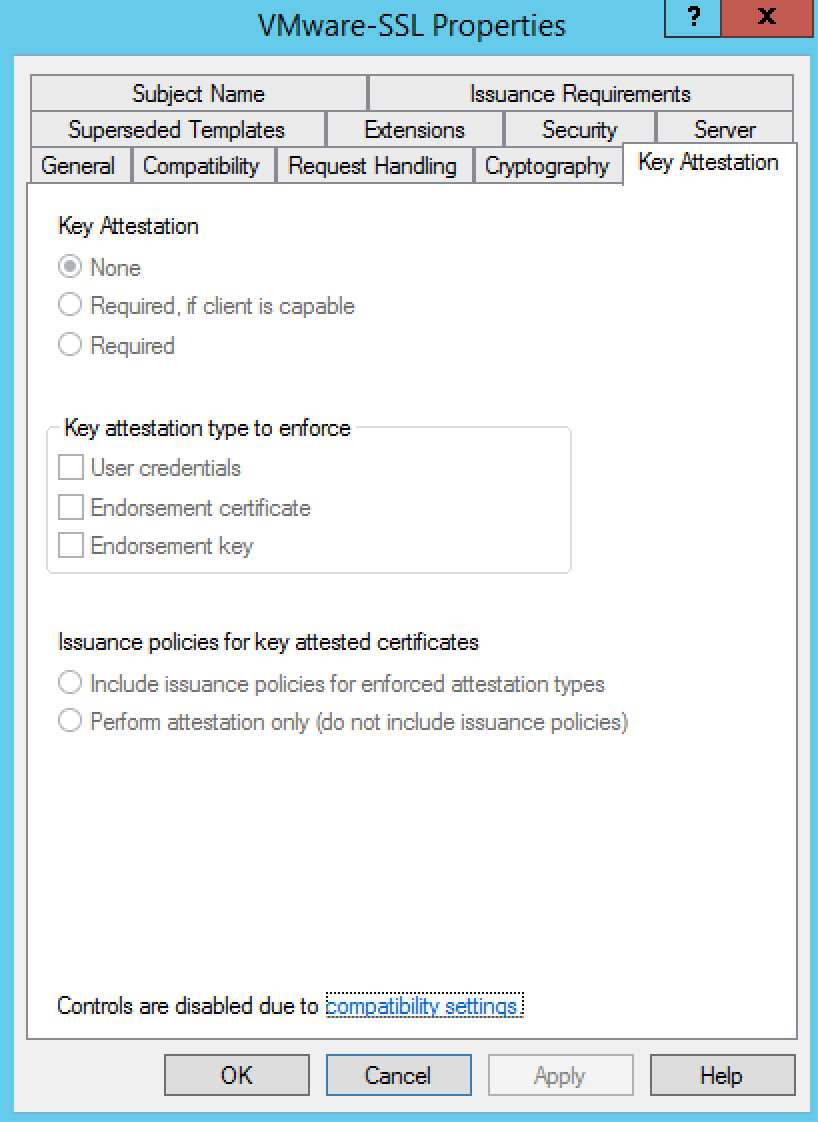
- You should see the Compatibility tab
- Select Windows Server 2008 R2 as the Certification Authority
- Select Windows 7 / Server 2008 R2 under Certificate recipient
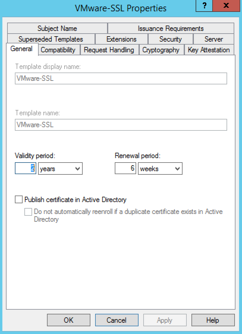
- Click the General tab.
- In the Template display name field, enter VMware-SSL as the name of the new template.
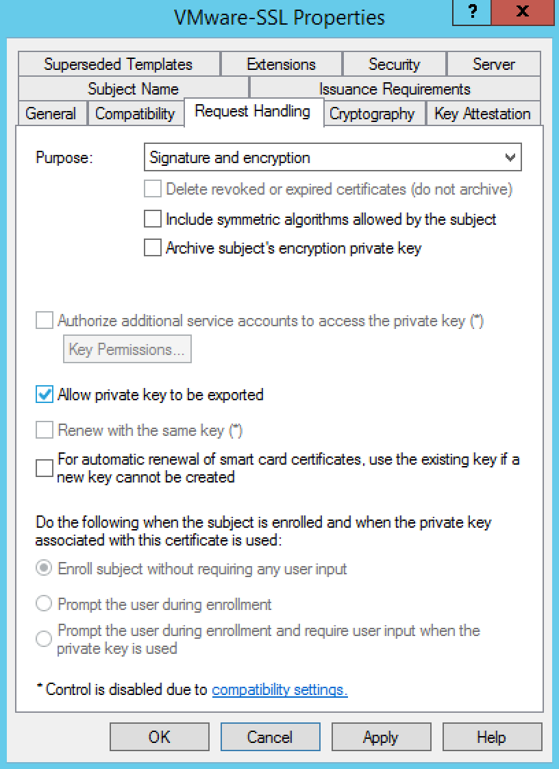
- Click the Request Handling tab
- Ensure that the Allow private key to be exported option is selected
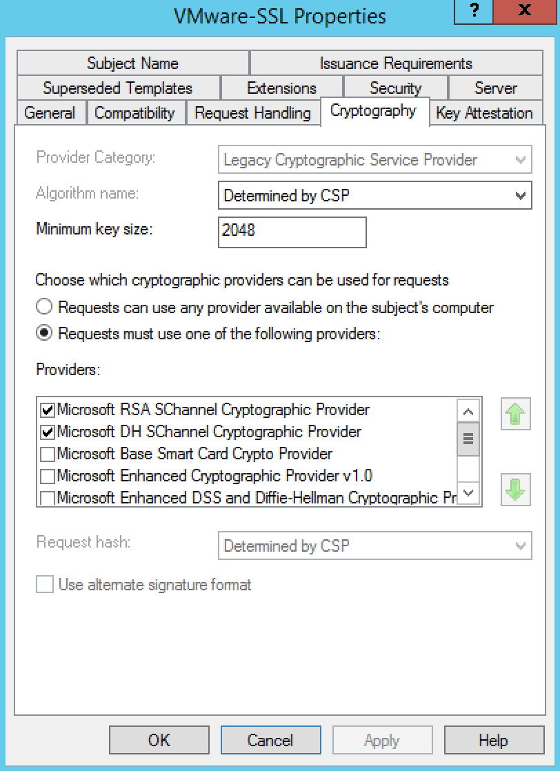
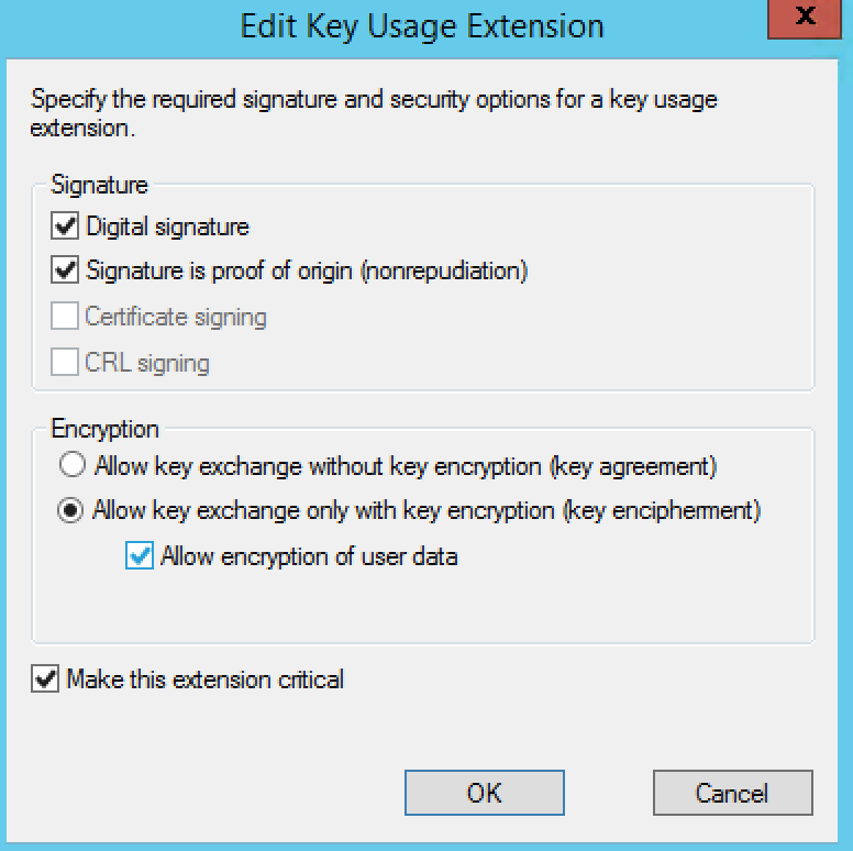
- Click the Edit button
- Select the Signature is proof of origin (nonrepudiation) option.
- Select the Allow encryption of user data option.
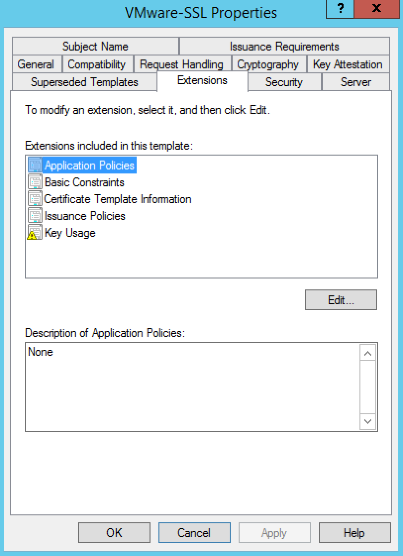
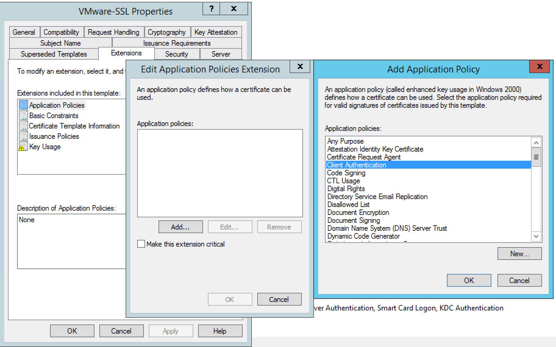
- Click Application Policies
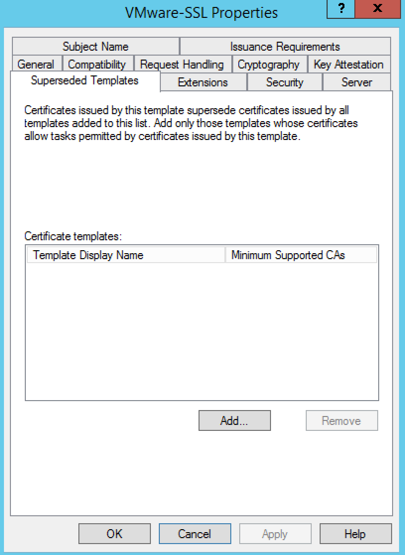
- Click Superseded Templates
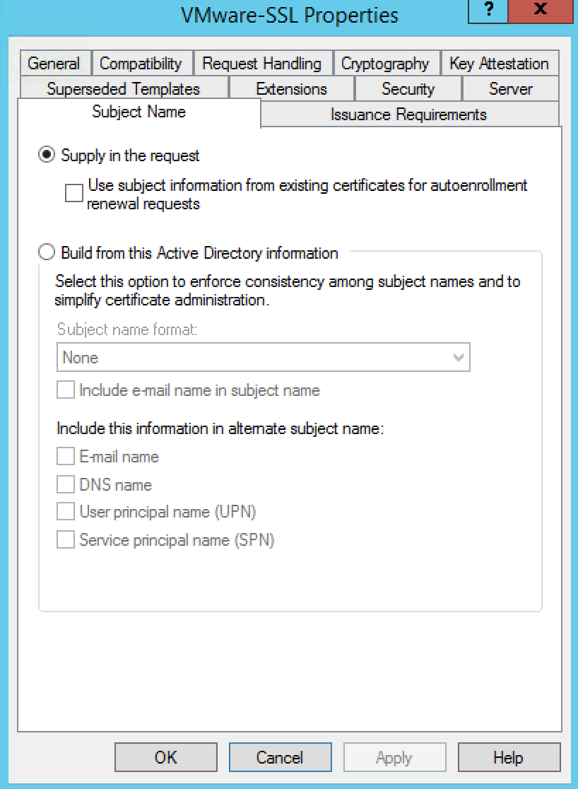
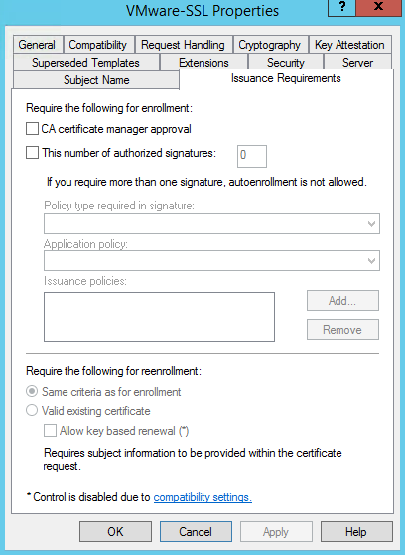
- Click Issuance Requirements
- Click OK to save the template.
Step 3 – Adding a new template to certificate templates
To add a new template to certificate templates:
- Connect to the Root CA server or Subordinate CA server via RDP.Note: Connect to the CA server in which you are intending to perform your certificate generation.
- Click Start > Run, type certsrv.msc, and click OK. The Certificate Server console opens.
- In the left pane, if collapsed, expand the node by clicking the [+] icon.
- Right-click Certificate Templates and click New > Certificate Template to Issue.
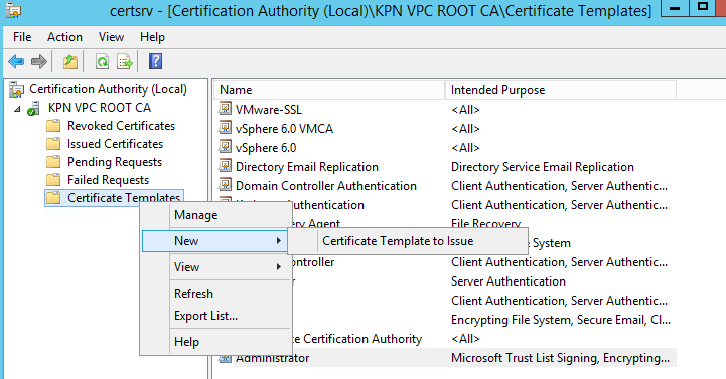
- Locate the VMware-SSL Certificate under the Name column.
- Click OK.
A new template option is now created in your Active Directory Certificate Services node. This new template can be used in the place of Web Server for the vSphere 5.x CA certificate.
Step 4 – Checking the web enrollment page
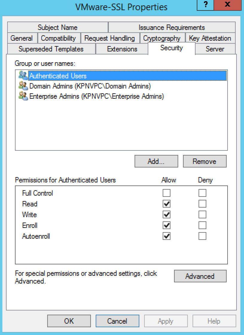
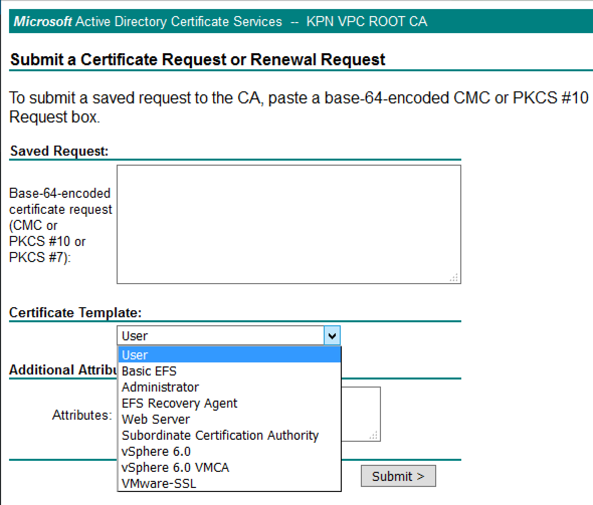
If everything went as planned you will have a new certificate template type when submitting a CSR. If you don’t see your new template, you may not have appropriate CA rights to issue the certificate.
- Navigate to https://yourcertificateserver/certsrv
- You should see the template VMware-SSL available
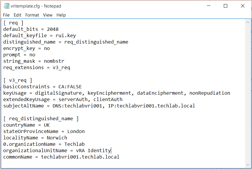
Step 5 – Creating a certificate configuration file for the Identity appliance
Useful Link
http://kb.vmware.com/selfservice/microsites/search.do?cmd=displayKC&docType=kc&docTypeID=DT_KB_1_1&externalId=2015387
- Copy the below text into a notepad file and save it as a .cfg file
- Modify the relevant parts of your appliance and company details
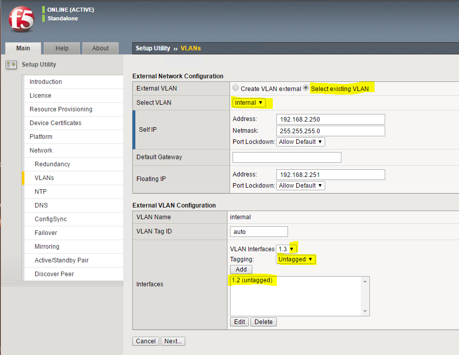
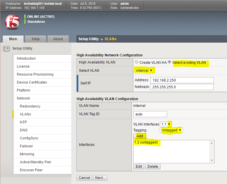
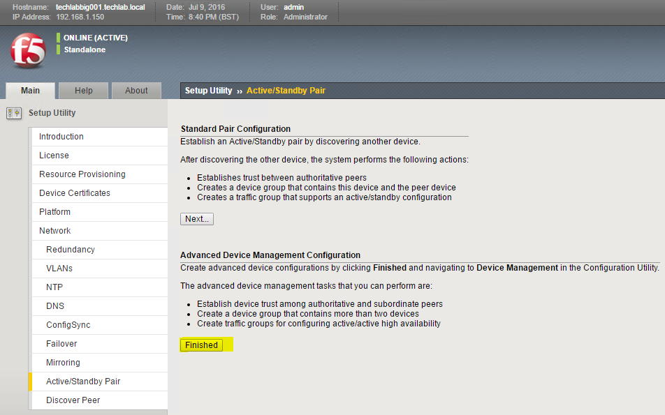
- Note you may have load balancers such as F5’s in which case you can also put the load balancer address in the subjectAltName section and the common name
[req]
default_bits = 2048
default_keyfile = rui.key
distinguished_name = req_distinguished_name
encrypt_key = no
prompt = no
string_mask = nombstr
req_extensions = v3_req
[v3_req]
basicConstraints = CA:FALSE
keyUsage = digitalSignature, keyEncipherment, dataEncipherment, nonRepudiation
extendedKeyUsage = serverAuth, clientAuth
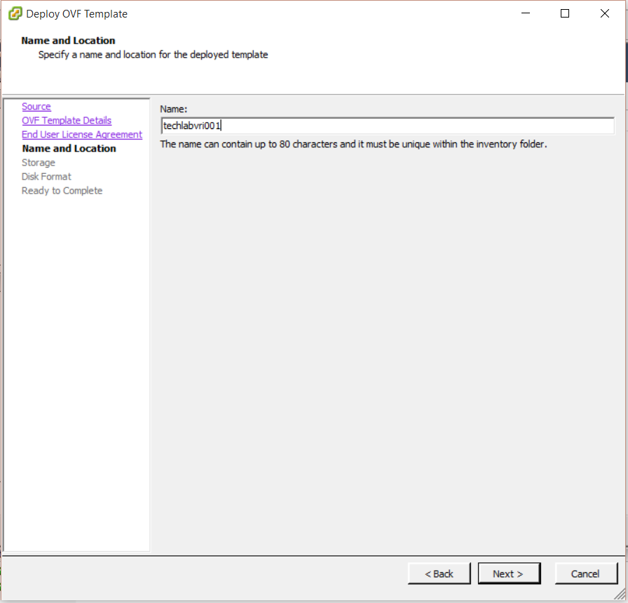
subjectAltName = DNS: techlabvri001, DNS: techlabvri001.techlab.local
[req_distinguished_name]
countryName = UK
stateOrProvinceName = London
localityName = Norwich
0.organizationName = Techlab
organizationalUnitName = vRA Identity
commonName = techlabvri001.techlab.local
- So it should look like this for the Identity Appliance
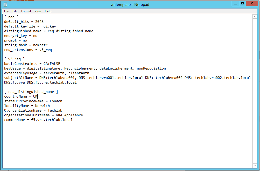
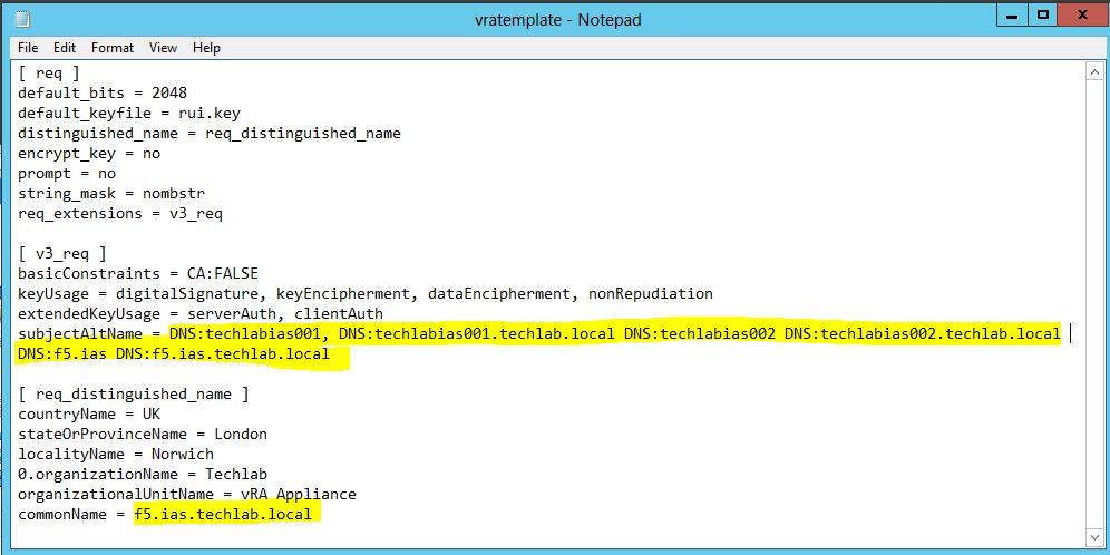
Step 5b – Creating a certificate configuration file for the Automation appliance
Note: I have put in both my vRA appliance hostnames and my load balanced name as I am going to cluster the vRA appliances
[ req ]
default_bits = 2048
default_keyfile = rui.key
distinguished_name = req_distinguished_name
encrypt_key = no
prompt = no
string_mask = nombstr
req_extensions = v3_req
[ v3_req ]
basicConstraints = CA:FALSE
keyUsage = digitalSignature, keyEncipherment, dataEncipherment, nonRepudiation
extendedKeyUsage = serverAuth, clientAuth
subjectAltName = DNS:techlabvra001, DNS:techlabvra001.techlab.local DNS: techlabvra002 DNS: techlabvra002.techlab.local DNS:f5.vra DNS:f5.vra.techlab.local
[ req_distinguished_name ]
countryName = UK
stateOrProvinceName = London
localityName = Norwich
0.organizationName = Techlab
organizationalUnitName = vRA Appliance
commonName = f5.vra.techlab.local
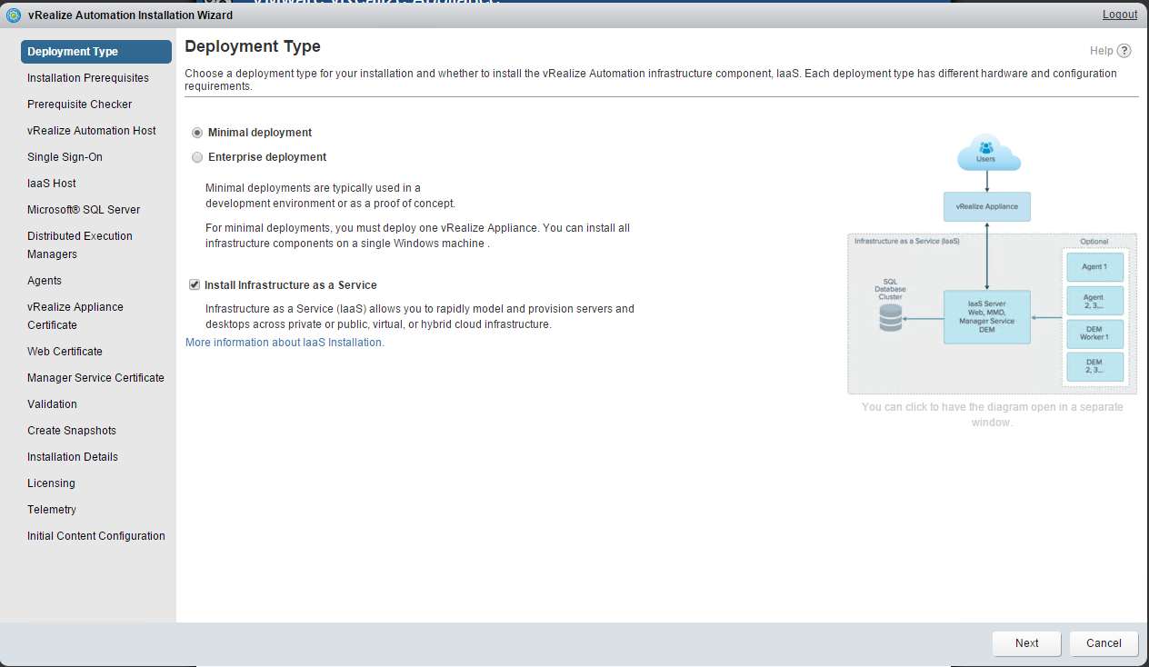
Step 6 Update components certificates in the following order:
- Identity Appliance
- vCloud Automation vCenter Appliance
- IaaS components
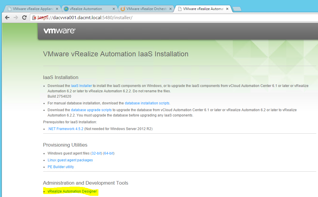
Step 7 – Installing OpenSSL version 0.9.8.
Use the following steps to install OpenSSL, which will be used to request the required certificates.
Important: Ensure that you are using OpenSSL version 0.9.8. If you do not use this version, the SSL implementation will fail.
- Ensure that the Microsoft Visual C++ 2008 Redistributable Package (x86) is installed on the system on which you want to generate the requests. To download the package, see the Microsoft Download Center
- Download the Shining Light Productions installer for OpenSSL x86 version 0.98r or later on the link below http://www.slproweb.com/products/Win32OpenSSL.html. This software was developed by the OpenSSL Project
- Launch the installer, proceed through the installation, and make a note of the appropriate directory for later use. By default, it is located at c:\OpenSSL-Win32.
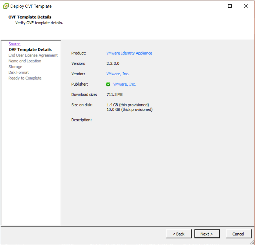
Step 8 – Generating certificates for the vRA Identity Appliance and the vRA Appliance
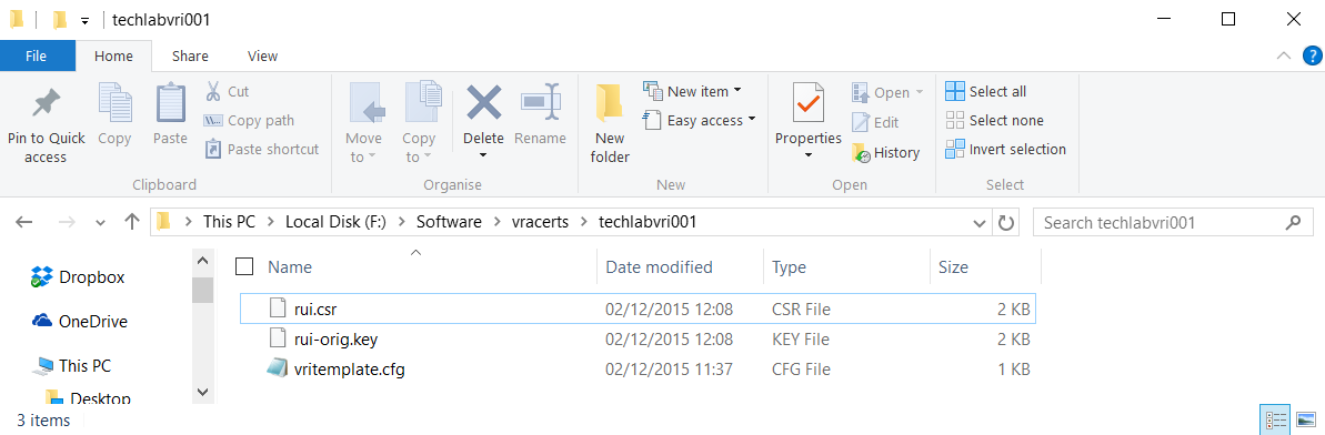
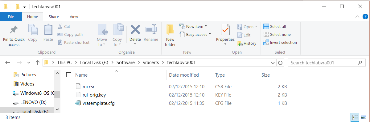
- Make sure you have your identity appliance and vra appliance config files in a folder (You will need to change the paths highlighted in blue to your own folder)
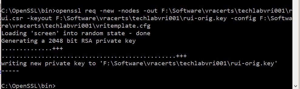
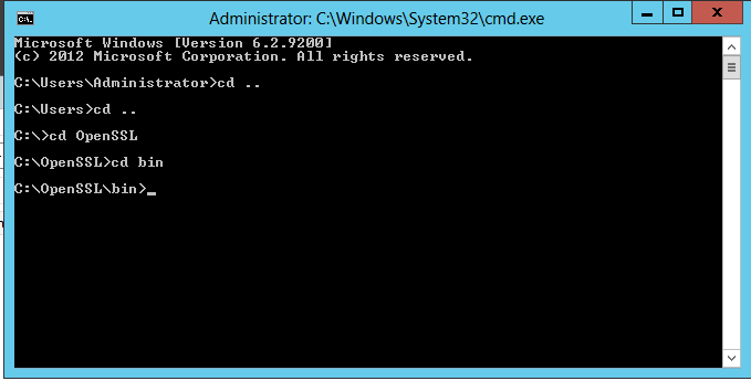
- Open cmd.exe and change directory to c:\OpenSSL\bin
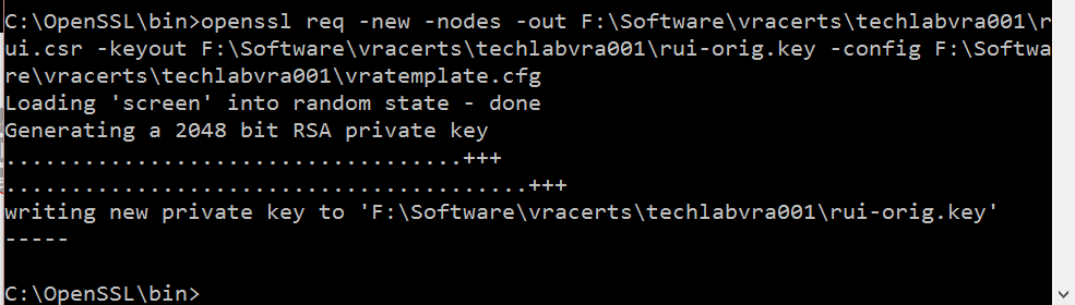
- Run the following commands
Identity
openssl req -new -nodes -out F:\Software\vracerts\techlabvri001\rui.csr -keyout F:\Software\vracerts\techlabvri001\rui-orig.key -config F:\Software\vracerts\techlabvri001\vritemplate.cfg
vRA Appliance
openssl req -new -nodes -out F:\Software\vracerts\techlabvra001\rui.csr -keyout F:\Software\vracerts\techlabvra001\rui-orig.key -config F:\Software\vracerts\techlabvra001\vratemplate.cfg
Step 9 Convert the keys to the appropriate RSA format required by the appliances
Identity
openssl rsa -in F:\Software\vracerts\techlabvri001\rui-orig.key -out F:\Software\vracerts\techlabvri001\rui.key
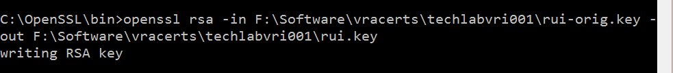
Appliance
openssl rsa -in F:\Software\vracerts\techlabvra001\rui-orig.key -out F:\Software\vracerts\techlabvra001\rui.key

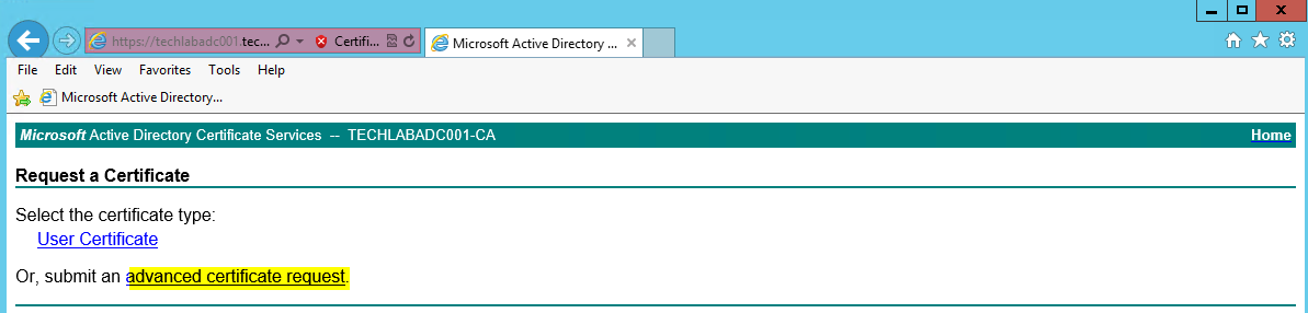
- Logon to the Microsoft CA Web Interface (https://ca-server/CertSrv)
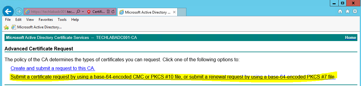
- Click on the Request Certificate > Advanced Certificate Request
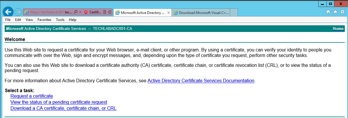
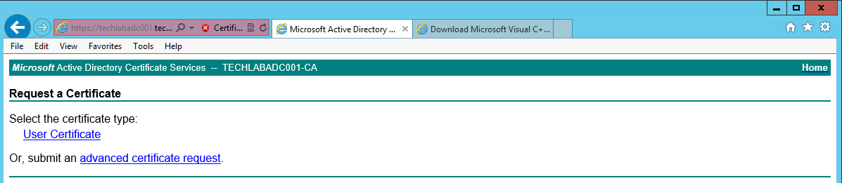
- Click Submit a certificate request by using a base-64-encoded CMC or PKCS #10 file, or submit a renewal request by using a base-64-encoded PKCS #7 file.
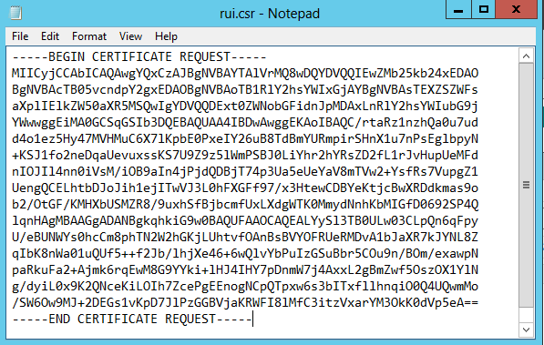
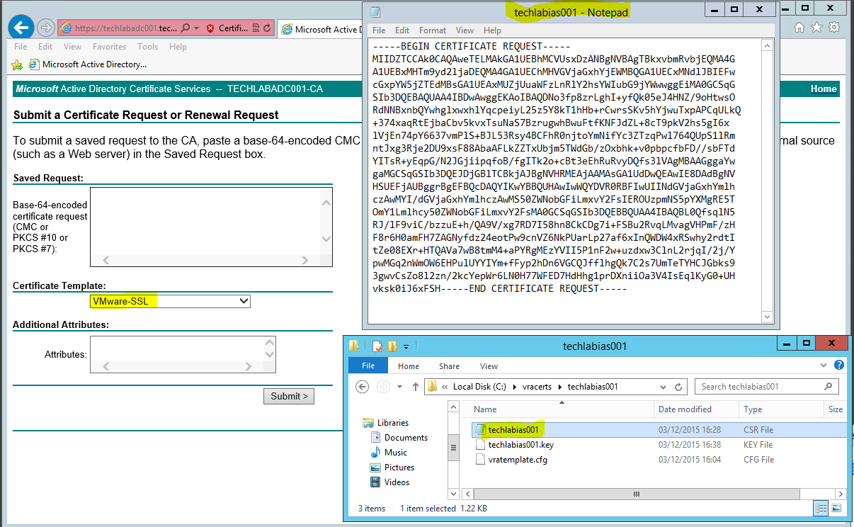
- Open the rui.csr file for the vCAC Identity Appliance and then copy and paste the contents into the Base-64-encoded certificate request field.
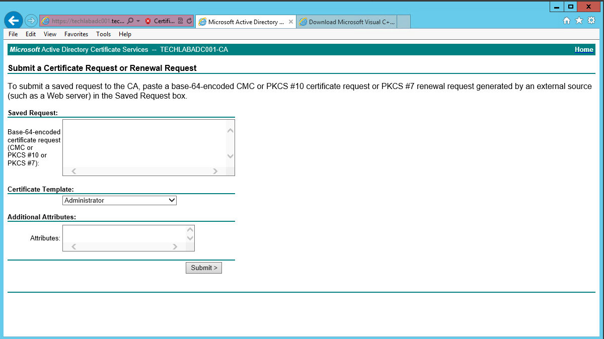
- Ensure you select the correctly configured Certificate Template
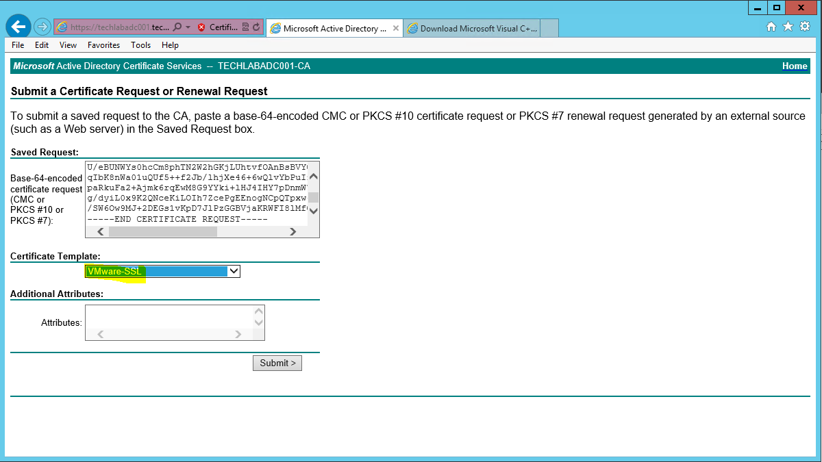
- Click “Submit” to submit the request.
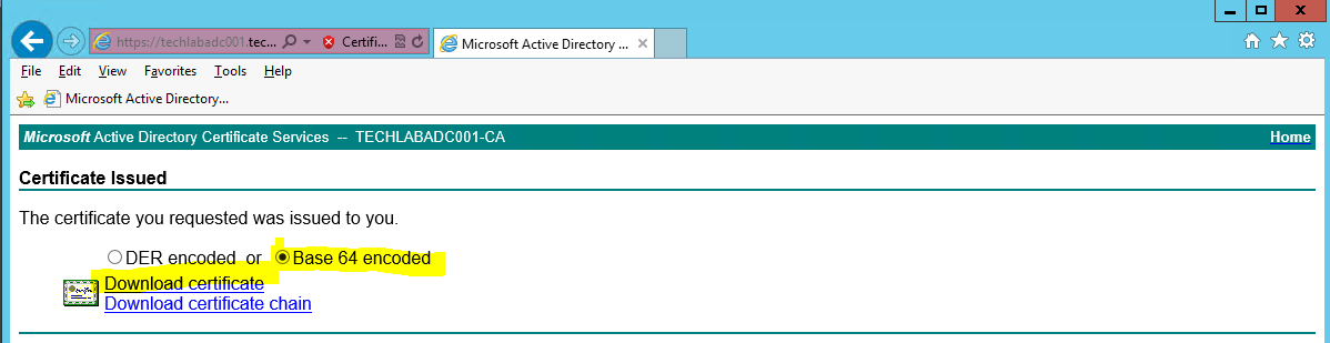
- Select the “Base64 encoded” option on the Certificate Issued screen.
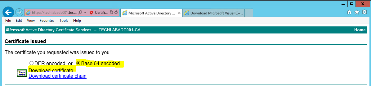
- Click the “Download Certificate” link and save as rui.crt in the same location as your config file and CSR.
- Repeat the above process for the vRA Appliance Certificate Request.
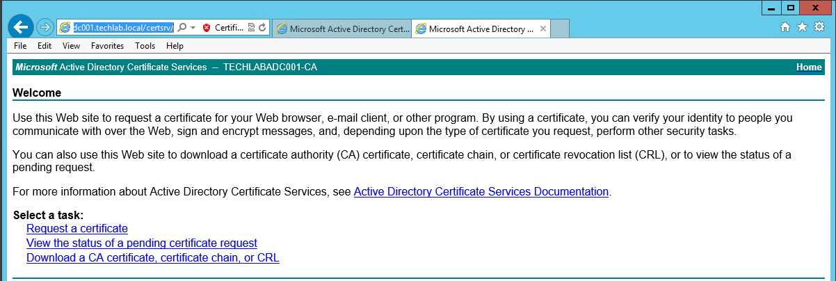
- Next go back to https://techlabadc001.techlab.local/certsrv/
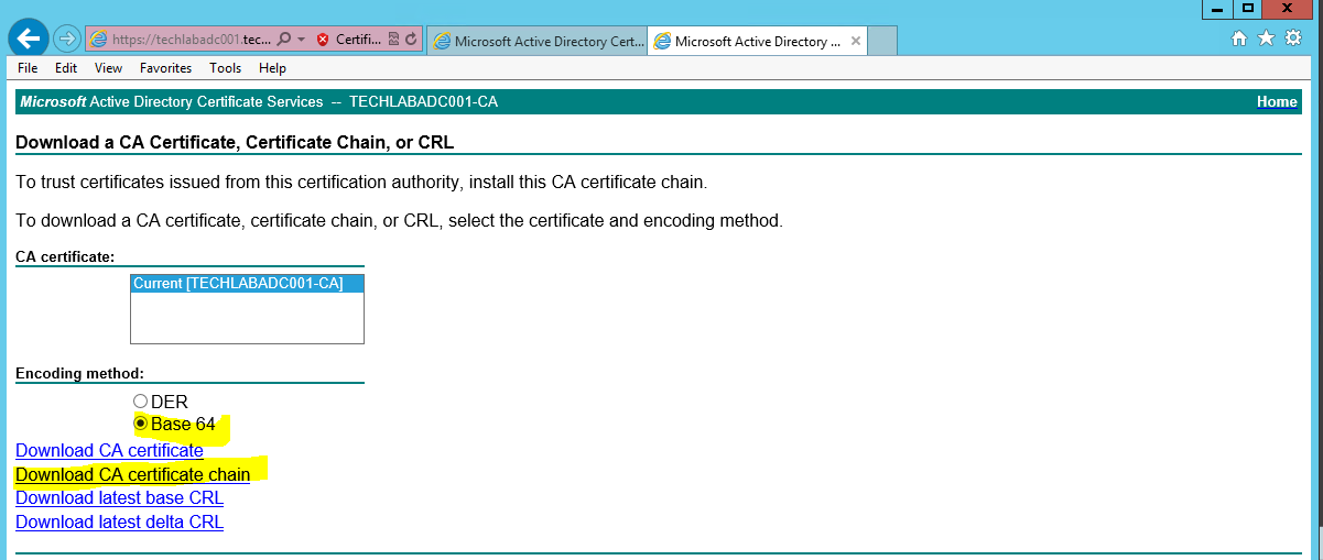
- Click on “Download a CA certificate, certificate chain or CRL”.
- Select the “Base64 encoded” option.
- Click the “Download a CA Certificate Chain” link.
- Save the certificate chain as cachain.p7b in your desired location
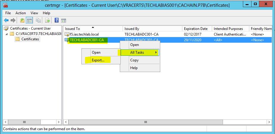
- Double click the cachain.p7b file and navigate to yourlocation\cachain.p7b > Certificates
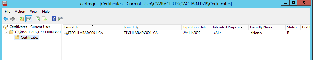
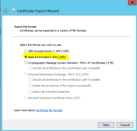
- Right click the root certificate and select “All Actions > Export” and then click Next.
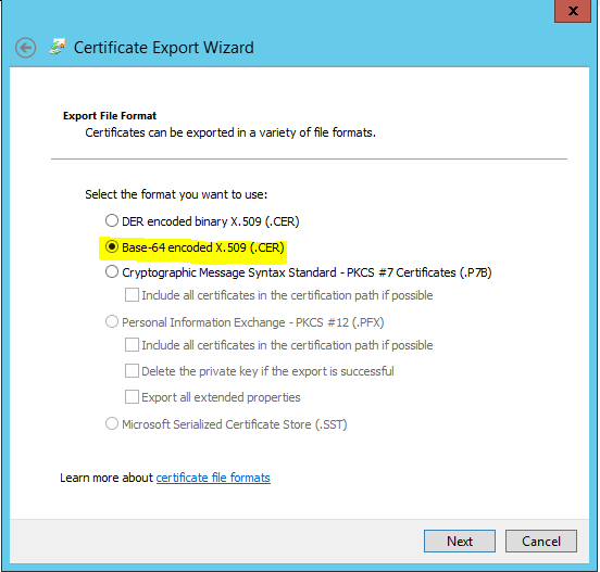
Select Base64-encoded X.509 (.CER) and click Next.
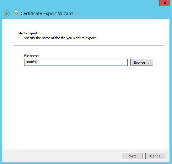
- Save the export to your location/root64.cer and click Next.
Converting the Certificates to PEM Format
- Launch a command prompt and navigate to your OpenSSL directory. By default this is located in c:\OpenSSL\bin
- Run the following commands (replacing the path with your desired location) to convert the certificates to the format expected of the Virtual Appliances.
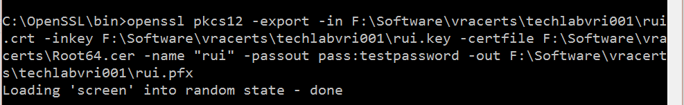
Identity
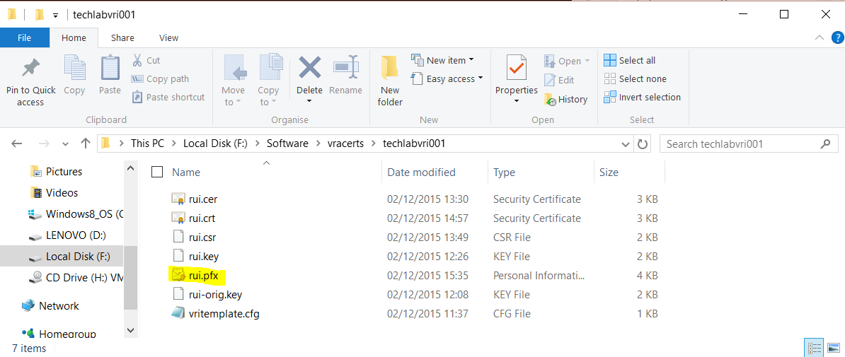
openssl pkcs12 -export -in F:\Software\vracerts\techlabvri001\rui.crt -inkey F:\Software\vracerts\techlabvri001\rui.key -certfile F:\Software\vracerts\Root64.cer -name “rui” -passout pass:testpassword -out F:\Software\vracerts\techlabvri001\rui.pfx
- You should then see your pfx file in the Identity appliance folder
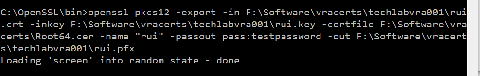
vRA Appliance
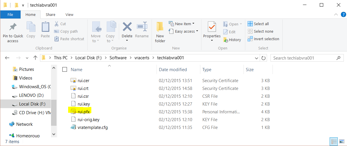
openssl pkcs12 -export -in F:\Software\vracerts\techlabvra001\rui.crt -inkey F:\Software\vracerts\techlabvra001\rui.key -certfile F:\Software\vracerts\Root64.cer -name “rui” -passout pass:testpassword -out F:\Software\vracerts\techlabvra001\rui.pfx
- You should then see your pfx file in the vRA appliance folder
- Next type the following commands
Identity
openssl pkcs12 -in F:\Software\vracerts\techlabvri001\rui.pfx -inkey F:\Software\vracerts\techlabvri001\rui.key -out F:\Software\vracerts\techlabvri001\rui.pem -nodes
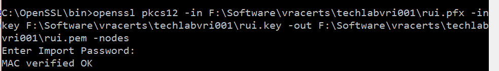
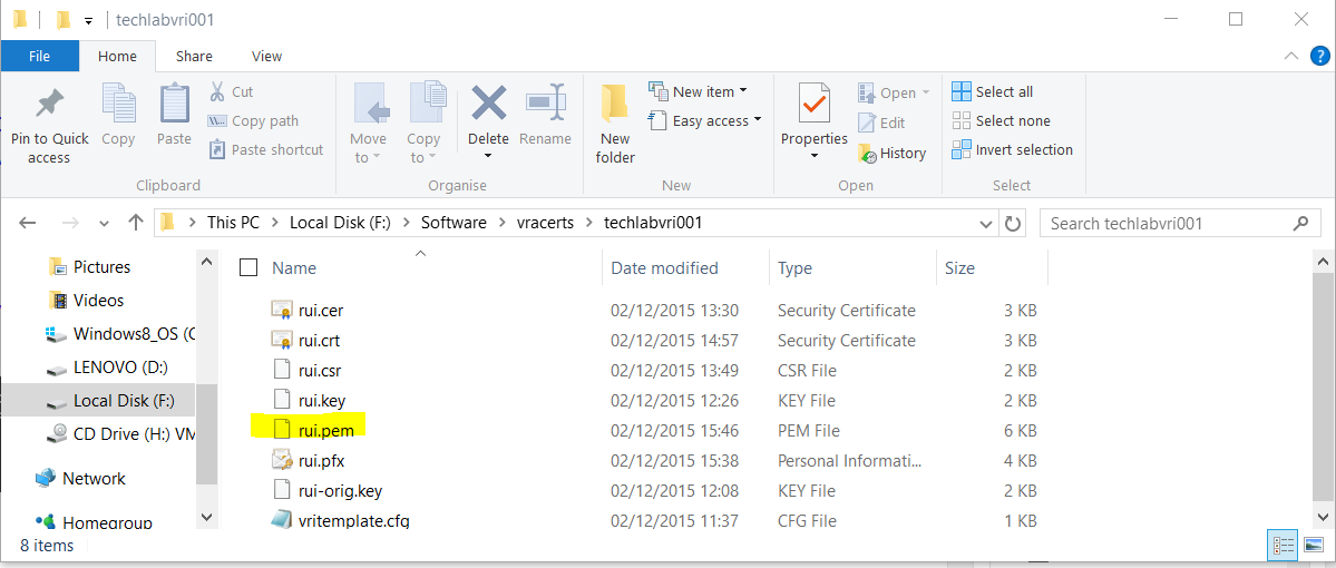
- You should now see the pem file
vRA Appliance
openssl pkcs12 -in F:\Software\vracerts\techlabvra001\rui.pfx -inkey F:\Software\vracerts\techlabvra001\rui.key -out F:\Software\vracerts\techlabvra001\rui.pem -nodes
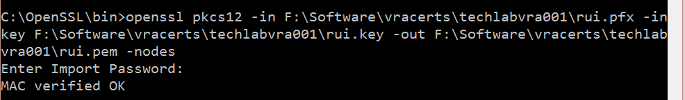
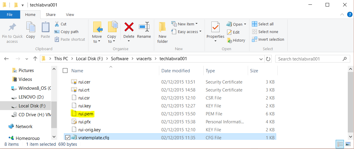
- You should now see the pem file
Note:
All of the above instructions worked for me but if the above command does not work to issue the PEM then try the below commands instead for vRA 6.2.
Someone reported that the pem creation syntax above seems to give the error “unable to create keystore” when installing the cert in the identity appliance in vRA 6.2.
These commands are listed in the vRA 6.2 document at
VMware vRealize Automation Center 6.2
openssl pkcs12 -in C:\certs\identity\rui.pfx -clcerts -nokeys -out C:\certs\identity\rui.pem
openssl pkcs12 -in C:\certs\vcaca\rui.pfx -clcerts -nokeys -out C:\certs\vcaca\rui.pem
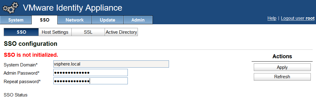
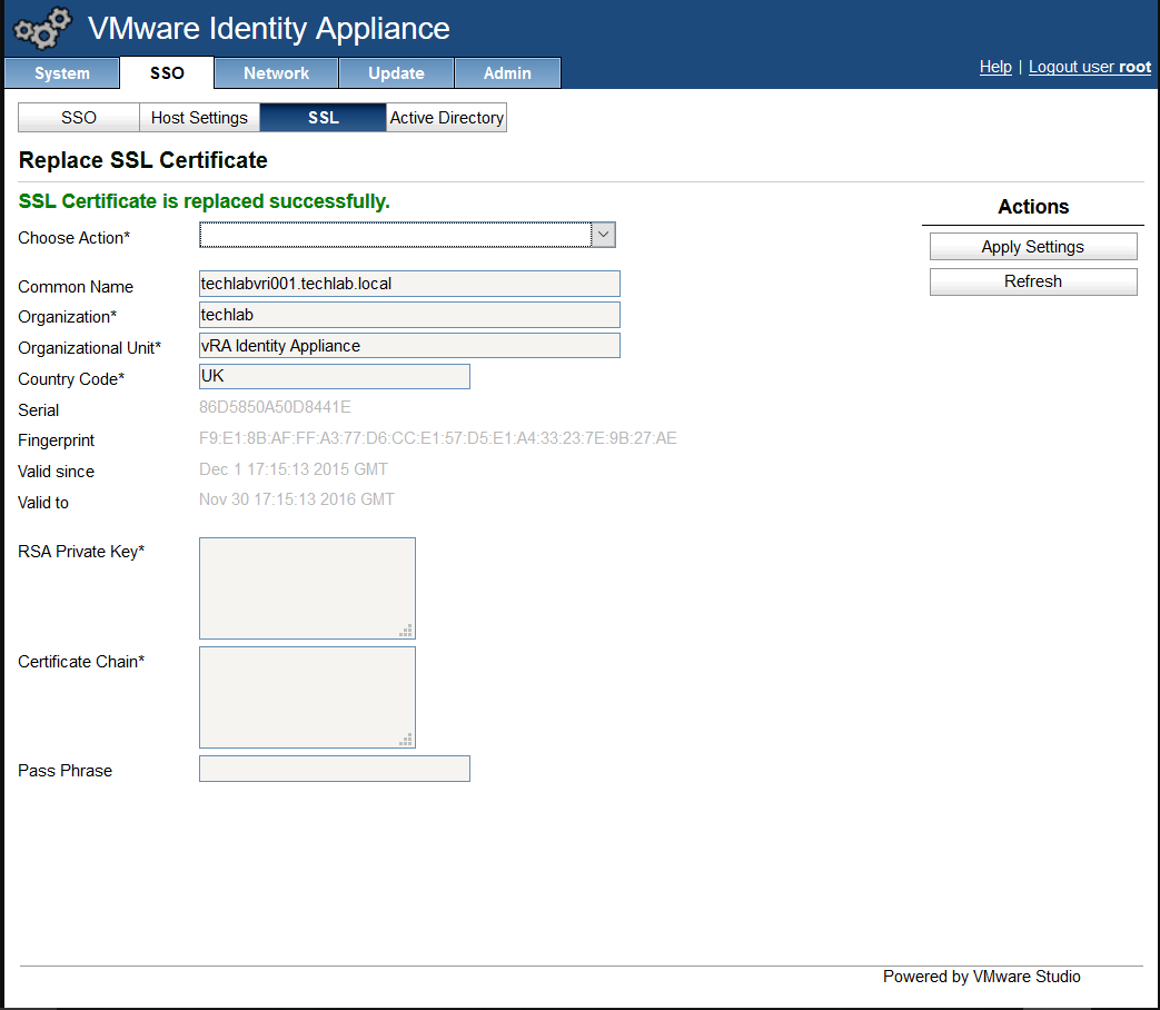
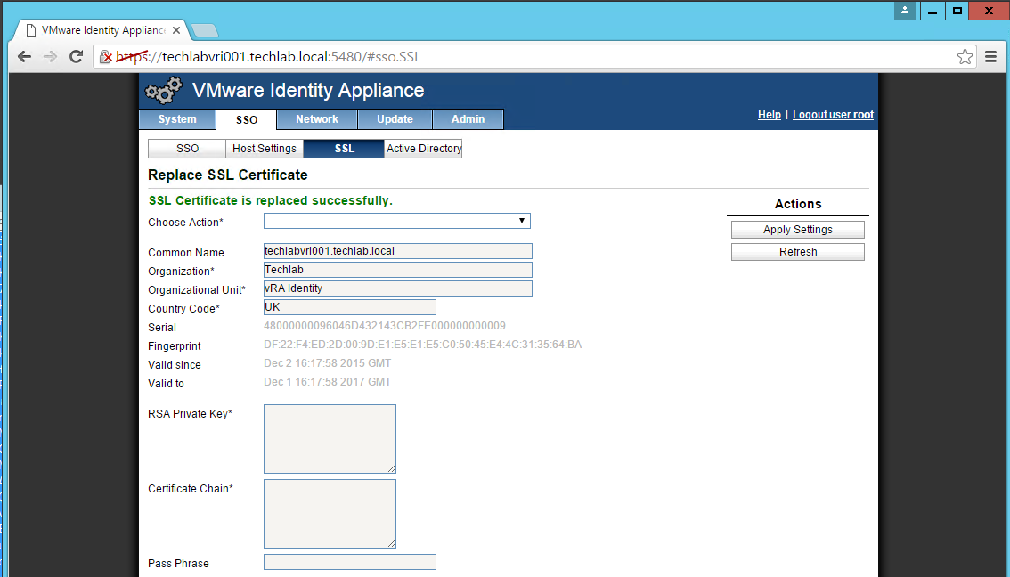
Importing the Certificate to your Identity Appliance
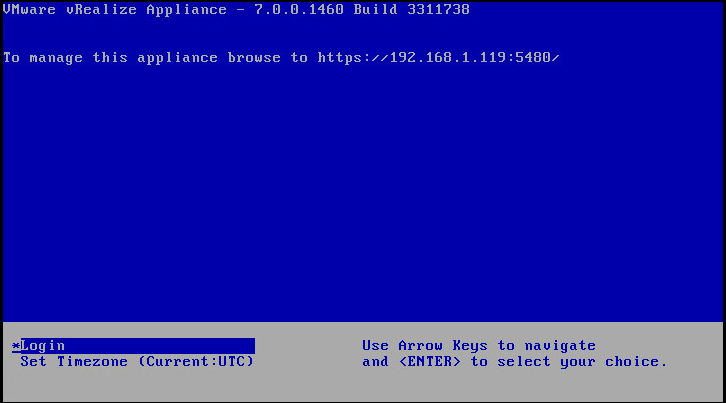
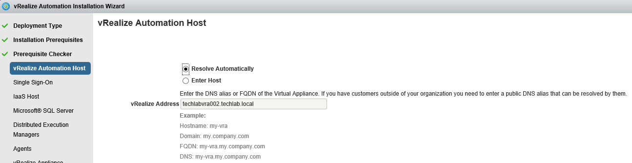
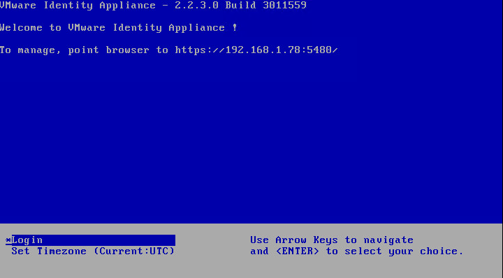
- Login to your identity appliance on https://vCAC.ID.FQDN:5480
- In my case https://techlabvri001.techlab.local:5480/
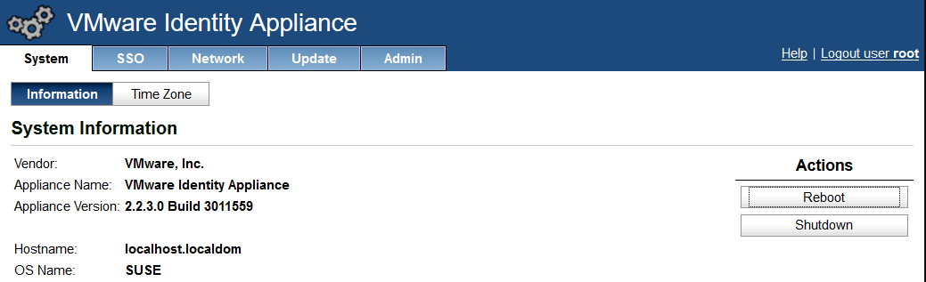
- Click on the SSO tab.
- Click on the SSL tab.
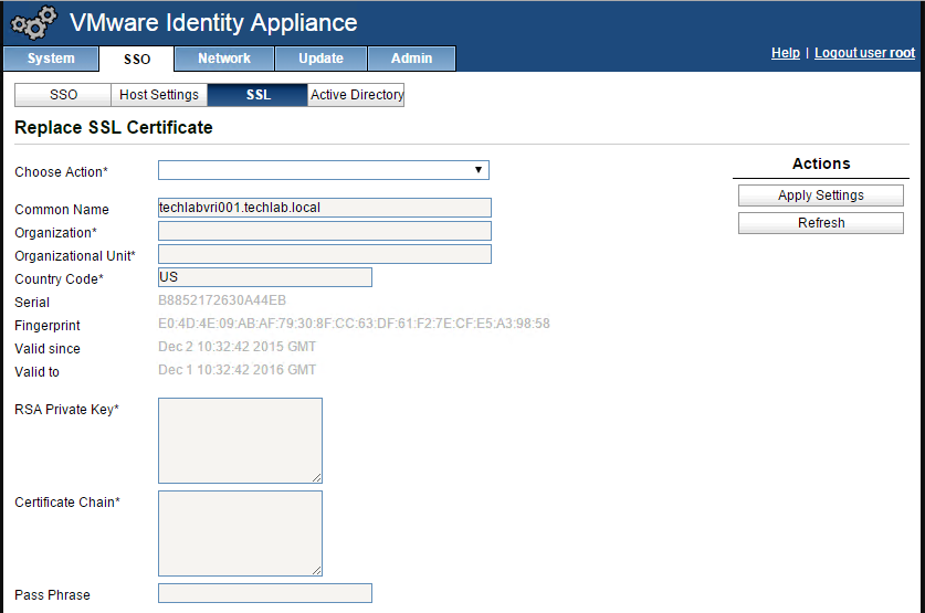
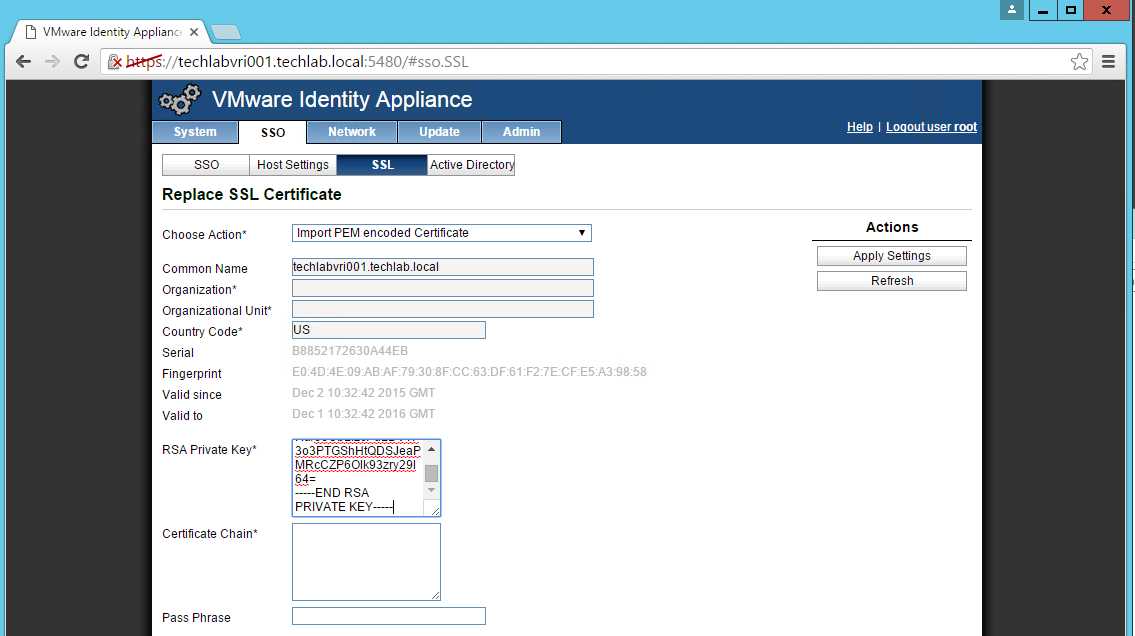
- In the “Choose Option” field, click the drop down and select Import PEM encoded certificate.
- Open the rui.key file for your vCAC ID appliance in a text editor.
- Copy and paste the contents into the “RSA Private Key” field.
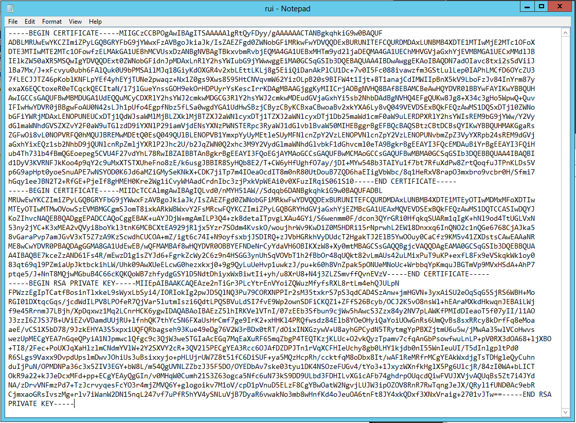
- Open the rui.pem file for your vRA Identity appliance in a text editor.
- Copy and paste the contents into the “Certificate” field.
- Note: It is really important that it looks like the below certificate. if you get any random lines other than these, you need to remove them or it will not work
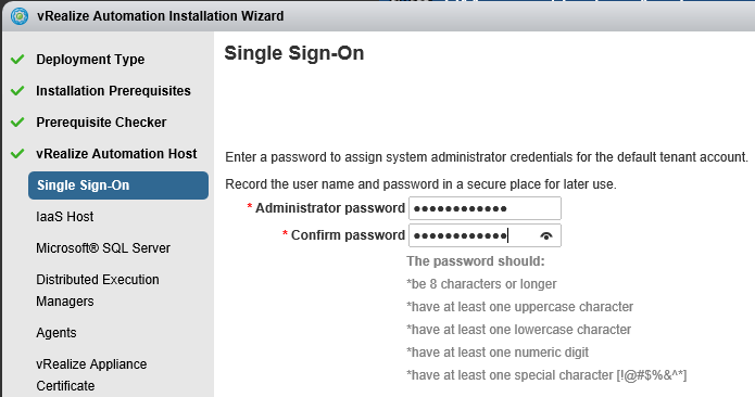
- Enter testpassword into the “Pass Phrase” field.
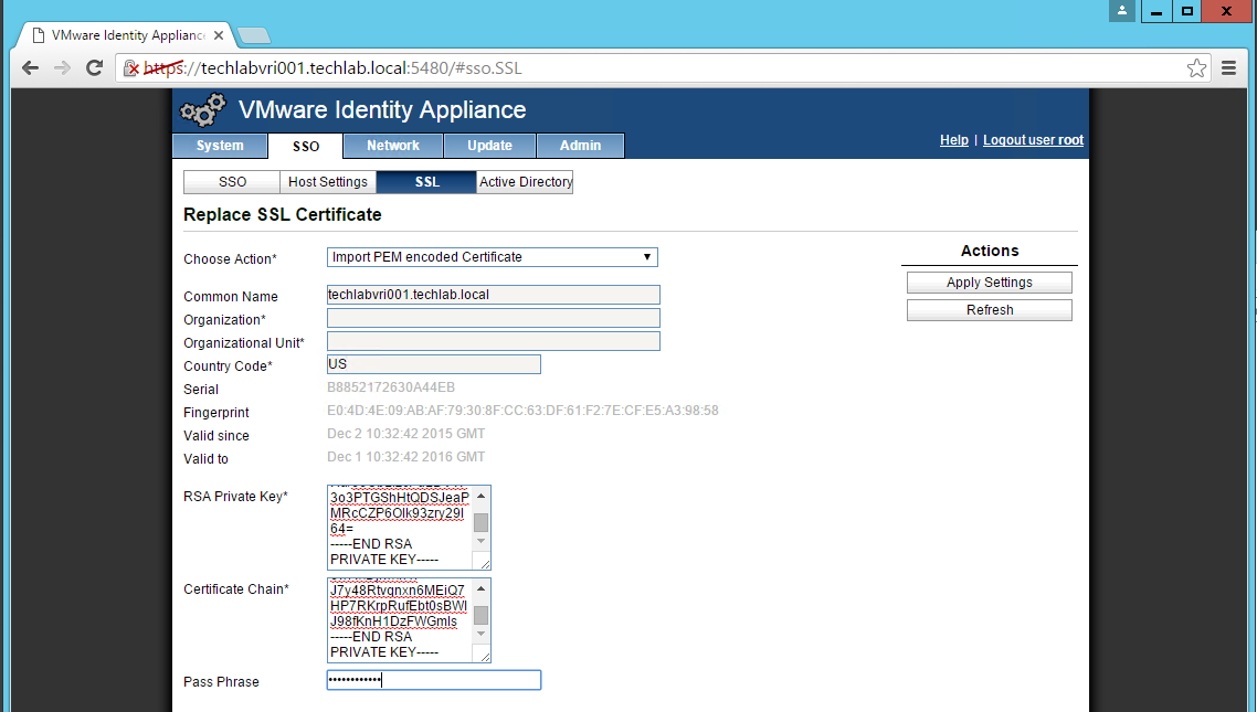
- Click the “Replace Certificate” button
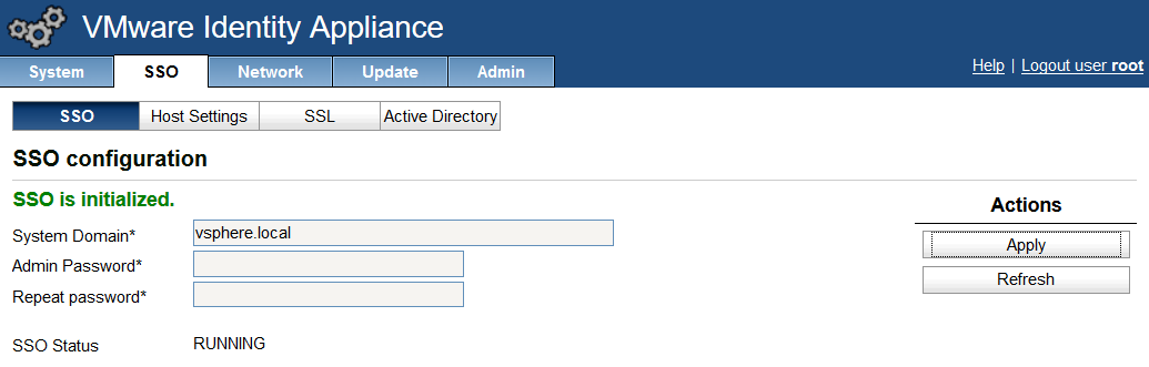
- You should now see the certificate imported
Importing the Certificate to your vRA Appliances
Note: Do this on both appliances!
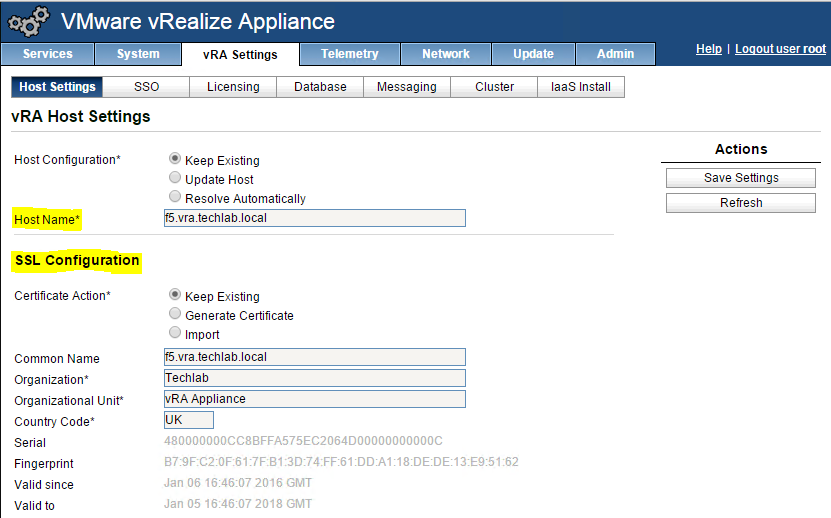
- Login to https://vRA.FQDN:5480
- Click on the vRA Settings tab > Host Settings > SSL Configuration
- In the “Choose Option” field, click the drop down and select Import PEM encoded certificate.
- Open the rui.key file for your vRA ID appliance in a text editor.
- Copy and paste the contents into the “RSA Private Key” field.
- Open the rui.pem file for you vRA ID appliance in a text editor.
- Copy and past the contents into the “Certificate” field.
- Enter testpassword into the “Pass Phrase” field.
- Click the “Replace Certificate” button.
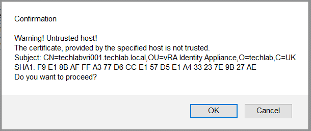
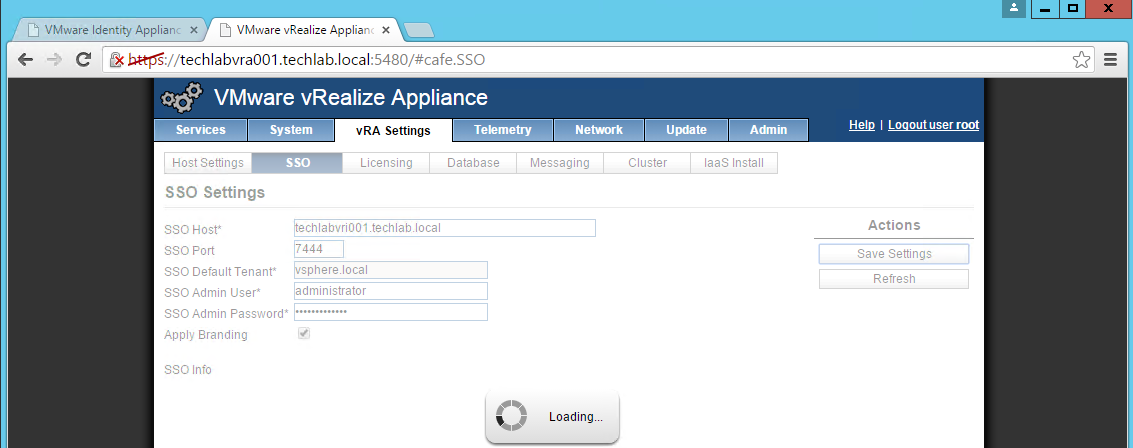
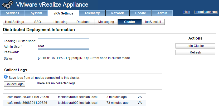
NOTE: If you are replacing the certificates after having registered the vRA VA against the vRA ID VA you will need to re-enter the SSO settings on the vCAC Server to ensure that communications between the VAs are trusted.
1. Login to https://vRA.FQDN:5480
2. Click on the vRA Settings tab then under Host Settings
3. Click on the SSO tab.
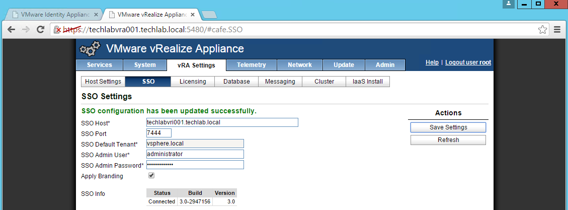
4. Re-enter the SSO Admin User and SSO Admin Password details and then click “Save Settings”.
Not performing this step will result in an error as shown below.
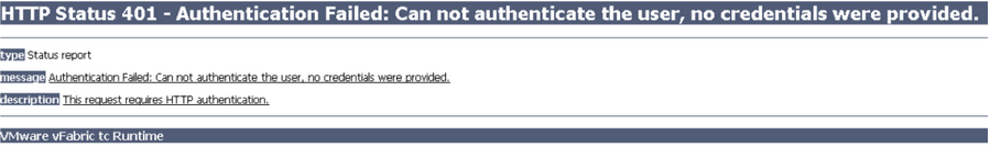
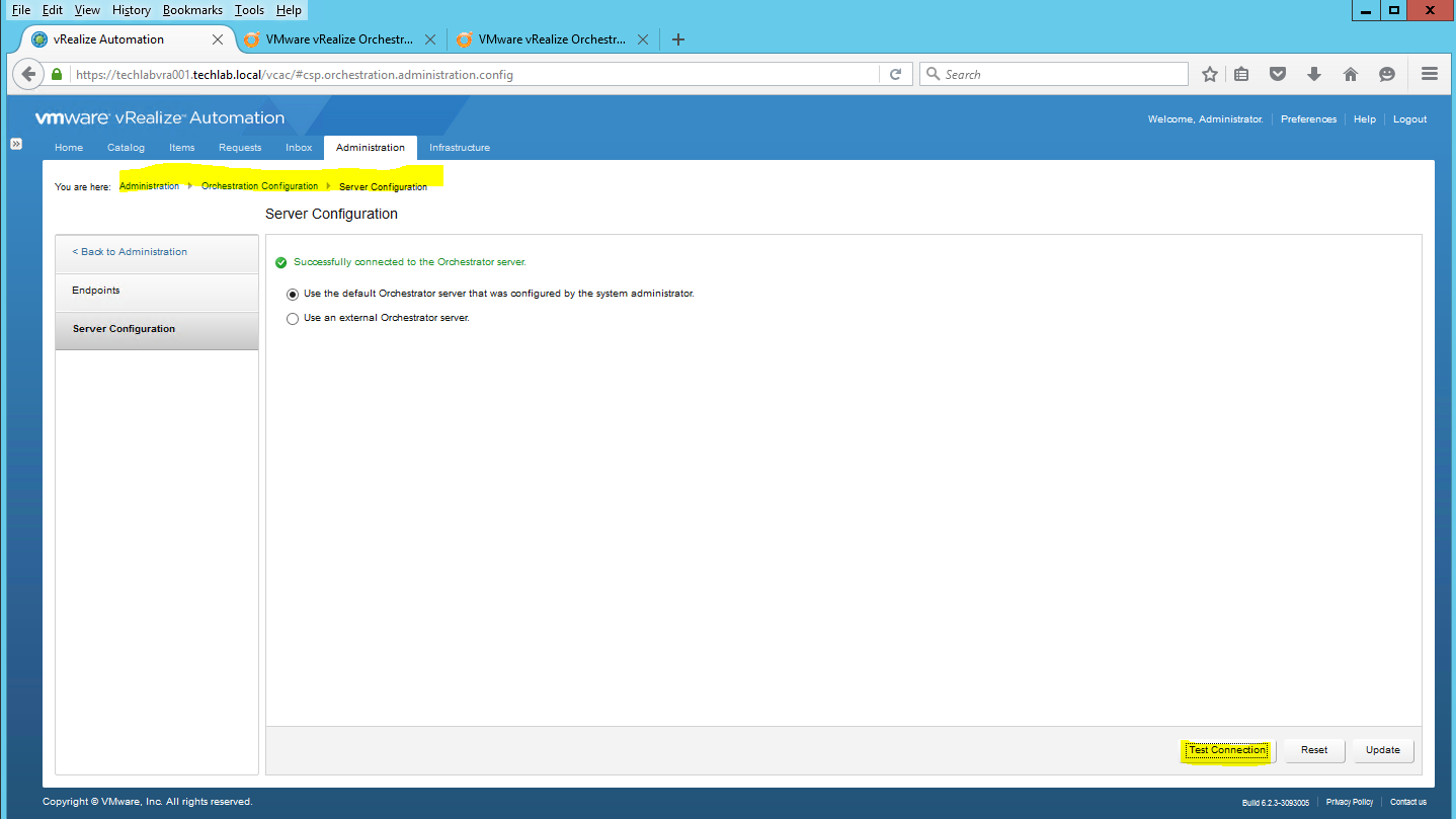
You should now see it is successful

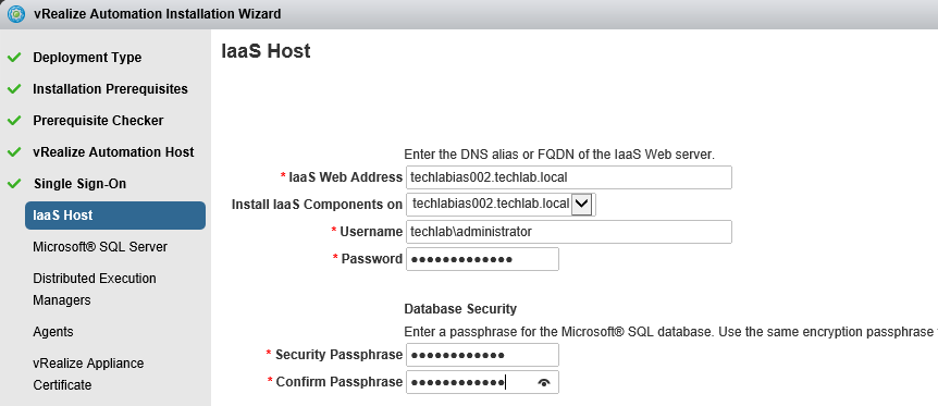
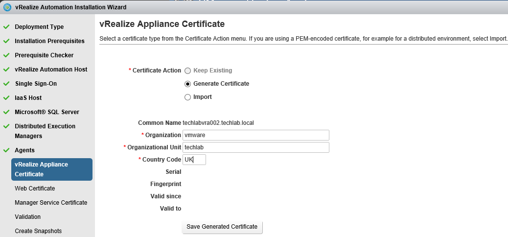
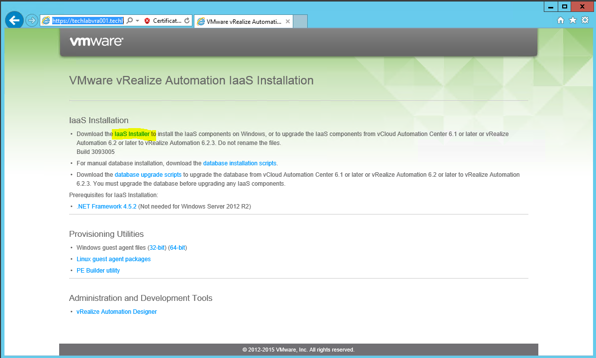
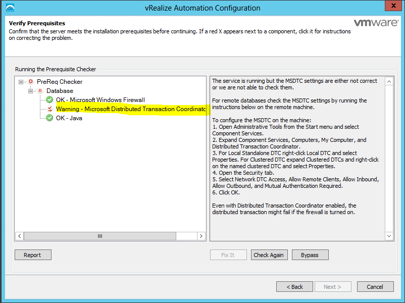
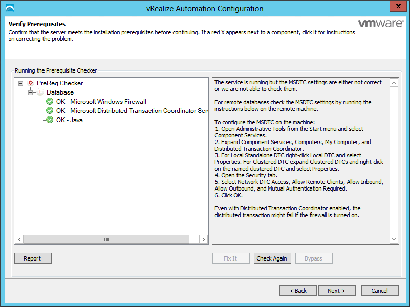
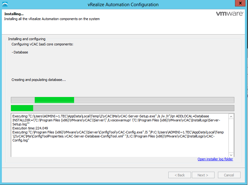
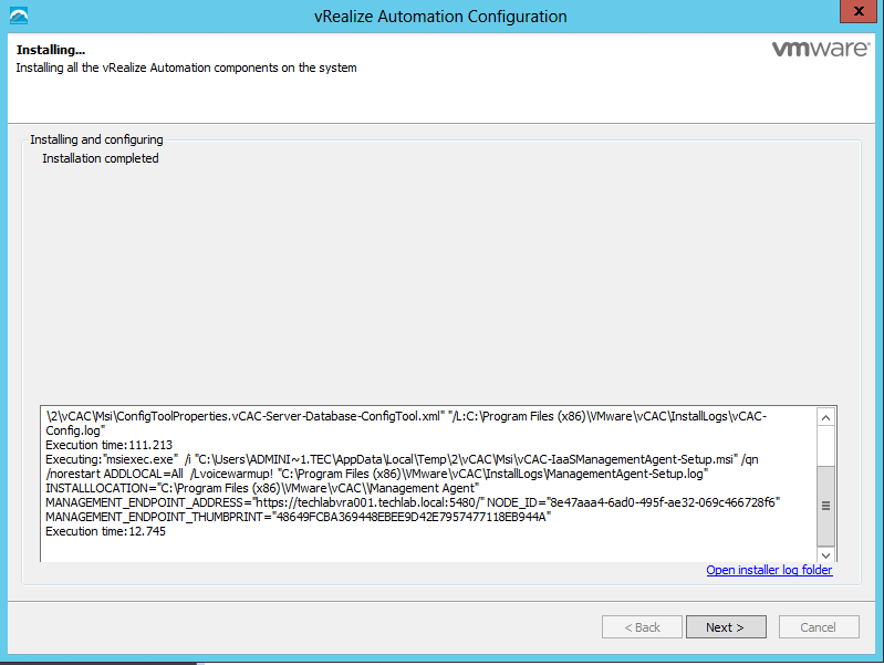
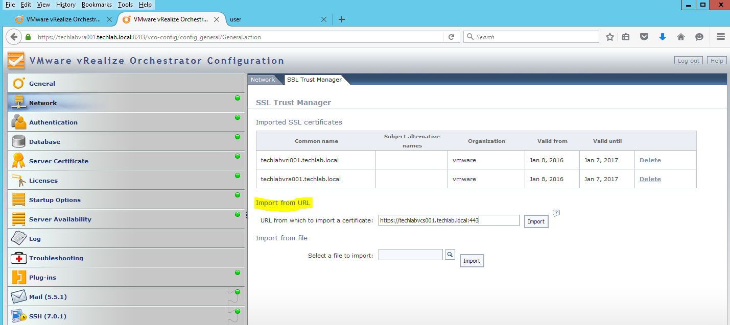
IaaS and Manager certificates
The order of operation is to first generate a PKCS12 formatted certificate. After a certificate is in PKCS12 format, it can be converted to PEM encoding and a DER encoded certificate can be generated from that PEM. In addition, an unencrypted key can be extracted from the PEM certificate
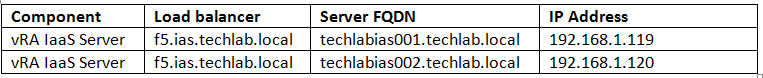
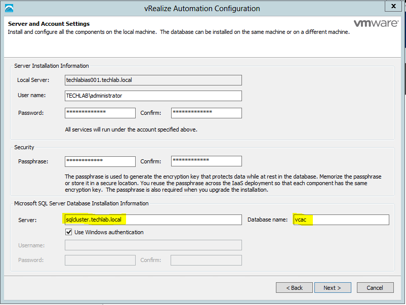
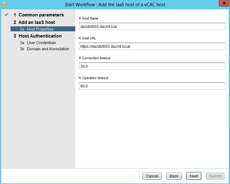
- First I generated a new certificate template called vratemplate.cfg
- I put in my 2 IaaS servers and the load balancer name in shorthand and FQDN.
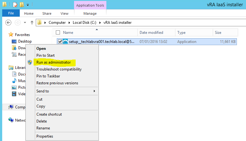
- Open cmd.exe as Administrator and navigate to the c:\OpenSSL\bin directory
- Run the following command replacing the highlighted parts with your own paths
- openssl req -new -nodes -out C:\vracerts\techlabias001\techlabias001.csr -keyout C:\vracerts\techlabias001\techlabias001.key -config C:\vracerts\techlabias001\vratemplate.cfg
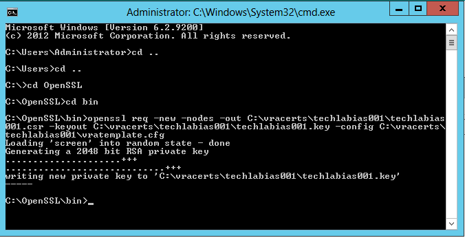
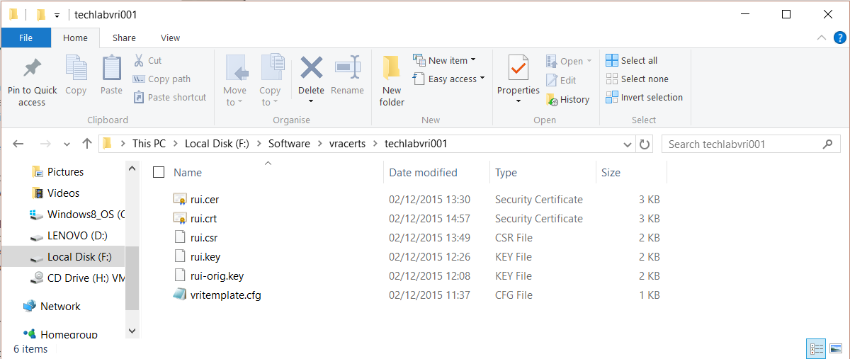
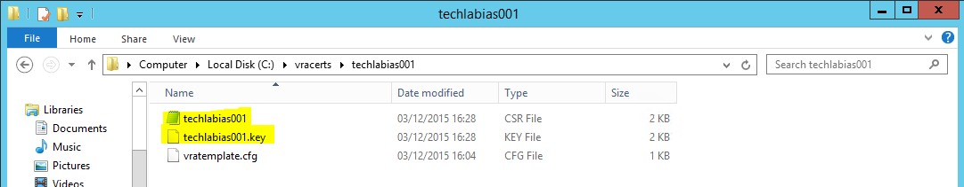
- You should see the following keys created
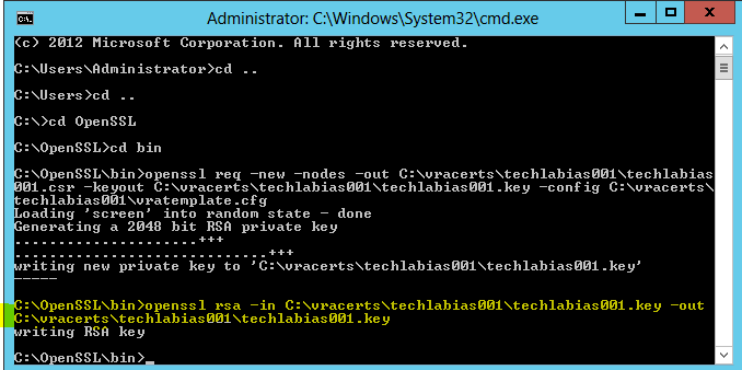
- Run the following command in OpenSSL to convert the keys to the RSA format required by the appliances
- openssl rsa -in C:\vracerts\techlabias001\techlabias001.key -out C:\vracerts\techlabias001\techlabias001.key
- Next go back to the certificate request home page
- Click Request a certificate
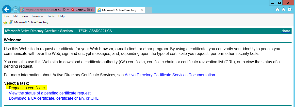
- Select Advanced certificate request
- Click Submit a certificate Request by using a base- 64-encoded CMC or PKCS #10 file, or submit a renewal request by using a base-64-encoded PKCS #7 file.
- Open the .csr file and copy the request into the box
- Make sure you select your VMware-SSL certificate
- Click Submit
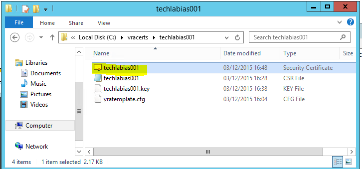
- Click on Download certificate and Base 64 encoded
- Save this certificate in your certificate folder. I named it techlabias001
- You will now see your certificate
- In the same page click on Download certificate chain
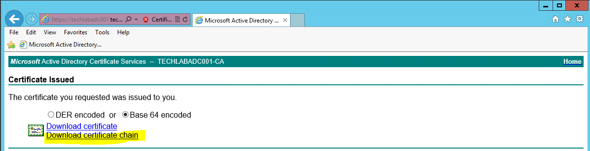
- Save the certificate as cachain.p7b
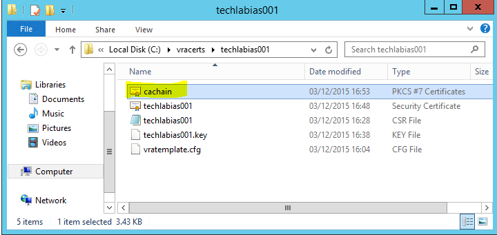
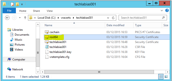
- Double click on this file and open it in the certificates console
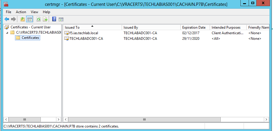
- Save the file as root64.cer
- You will see it as per below in your folder
- Go back to OpenSSL and run the command to convert the certificates to PKCS format
- openssl pkcs12 -export -in C:\vracerts\techlabias001\techlabias001.crt -inkey C:\vracerts\techlabias001\techlabias001.key -certfile C:\vracerts\techlabias001\root64.cer -name techlabias001 -passout pass:testpassword -out C:\vracerts\techlabias001\techlabias001.pfx
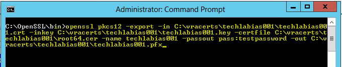
You will now see your .pfx file in the folder
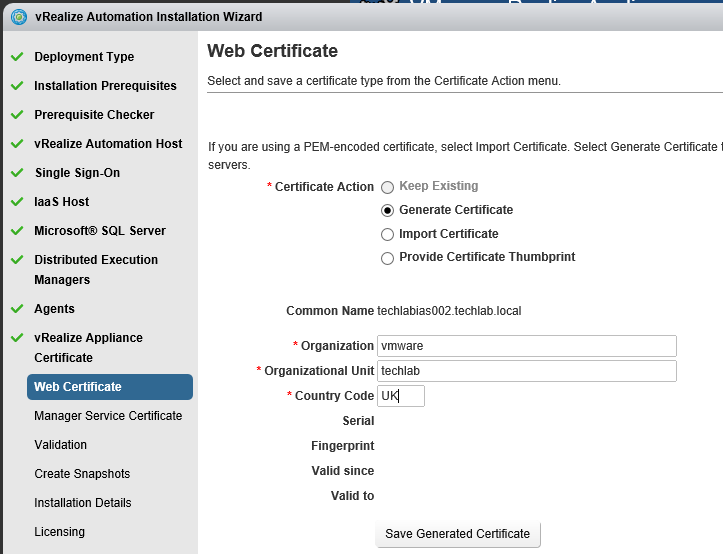
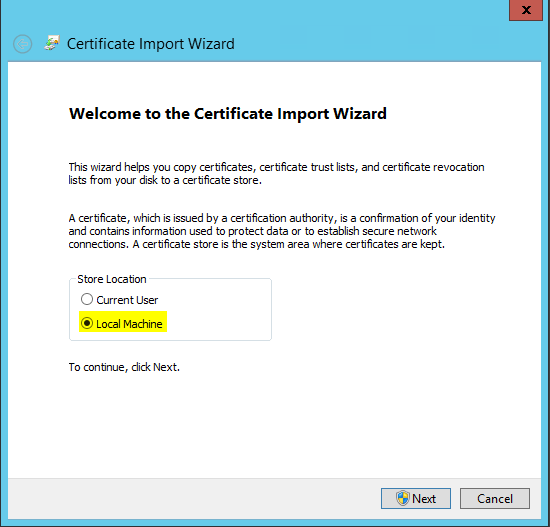
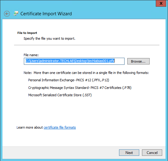
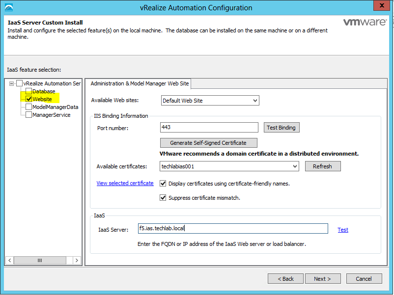
- Next we need to import the CA issued certificate for the IaaS web server.
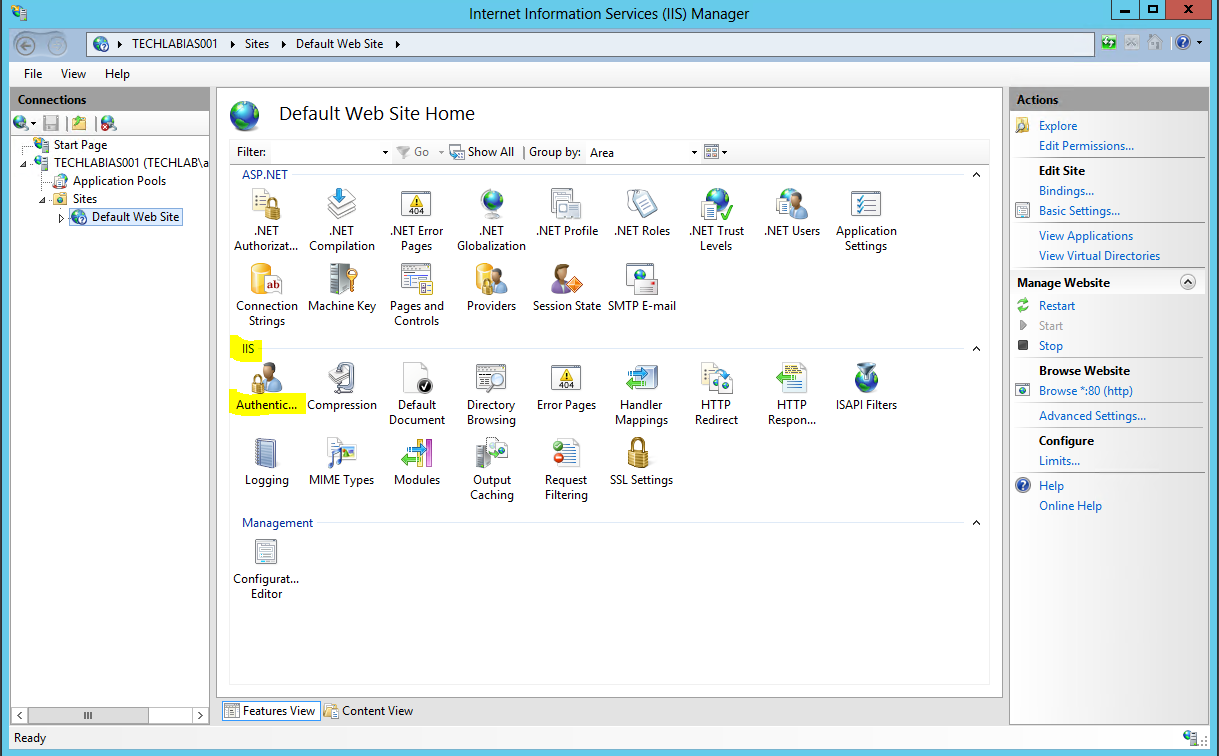
- On the IaaS server, open the IIS Manager console.
- Navigate to your Server instance, and open Server Certificates.
- Select “Import” in the top right hand corner.
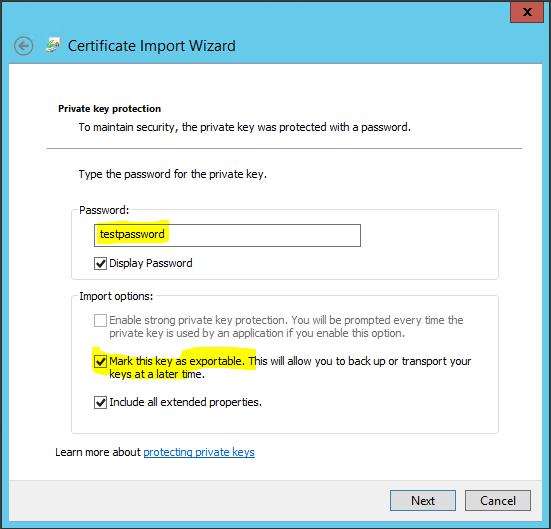
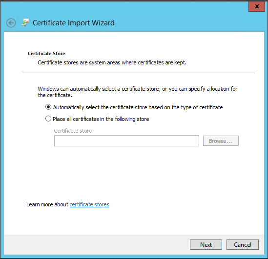
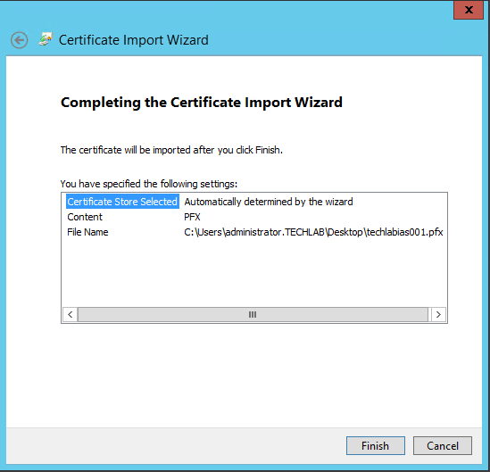
- In File name, browse and select the PKCS file with the .pfx extension that represents the CA issued certificate for IaaS web server.
- Type the password testpassword
- Accept the default Place all certificates in the following store.
- You should now see the imported certificate in your list
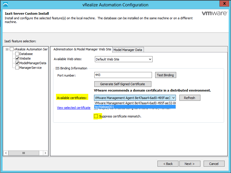
- Navigate to your Default Web Site (the vCAC website) and select “Bindings”.
- Select “https” and click “Edit”.
- Click the SSL Certificate drop down and select your certificate, then click OK.
Note: The below information doesn’t need to be done. It’s just information I put here to remind me to look at in relation to replacing certificates
Register the new Certificate with the vCAC Appliance
- Browse to c:\Program Files (x86)\VMware\vCAC\Server\Model Manager Data\cafe
- Note: CAFE stands for Cloud Automation Framework Extensibility. Just in case you were wondering
- Register the new certificates on your IaaS Server to the vCAC Appliance with the following set of commands:
vcac-config RegisterEndpoint –EndpointAddress https://techlabias001.techalab.local/vcac –Endpoint ui -v
vcac-config RegisterEndpoint –EndpointAddress https://techlabias001.techalab.local/vcac/SslCallback.aspx –Endpoint ssl -v
vcac-config RegisterEndpoint –EndpointAddress https://techlabias001.techalab.local/Repository –Endpoint repo -v
vcac-config RegisterEndpoint –EndpointAddress https://techlabias001.techalab.local/WAPI –Endpoint wapi -v
vcac-config RegisterEndpoint –EndpointAddress https://techlabias001.techalab.local/WAPI/api/status –Endpoint status -v
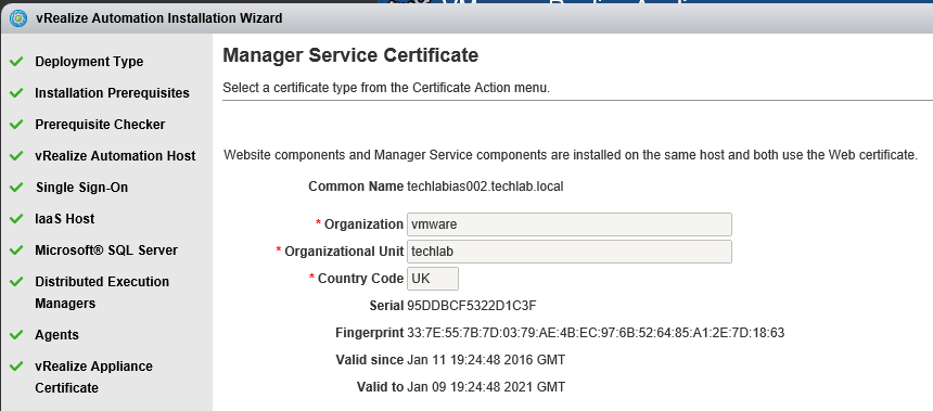
- Now you need to follow the exact same steps to generate the manager certificate