
What are IPv6 Transition Mechanisms?
IPv6 transition mechanisms are technologies that facilitate the transitioning of the Internet from its initial (and current) IPv4 infrastructure to the successor addressing and routing system of Internet Protocol Version 6 (IPv6). As IPv4 and IPv6 networks are not directly interoperable, these technologies are designed to allow hosts on either network to participate in networking with the opposing network.
IPv6 is the next generation Internet protocol. Although IPv6 standardization efforts have been on going for over a decade, recent attention to IPv6 has increased because of IPv4 address shortages, mobility requirements, and the need for global, secure, seamless, and permanent connectivity. The next generation Internet that uses IPv6 promises to enable a whole new breed of applications.
Types of Nodes
- IPv4-only node. A node that uses only IPv4 and has only IPv4 addresses assigned
- IPv6/IPv4 node. A node that uses both IPv4 and IPv6.
- IPv6-only node. A node that uses only IPv6 and has only IPv6 addresses assigned
- IPv6 node. An IPv6 node can be an IPv6-only node or an IPv6/IPv4 node.
- IPv4 node. An IPv4 node can be an IPv4-only node or an IPv6/IPv4 node.
The Mechanisms
- Dual IP layer (also known as dual stack): A technique for providing complete support for both Internet protocols — IPv4 and IPv6 — in hosts and routers
- Configured tunnelling of IPv6 over IPv4: A technique for establishing point-to-point tunnels by encapsulating IPv6 packets within IPv4 headers to carry them over IPv4 routing infrastructures
Dual IP Layer Operation
The most straightforward way for IPv6 nodes to remain compatible with IPv4-only nodes is by providing a complete IPv4 implementation. IPv6 nodes that provide complete IPv4 and IPv6 implementations are called “IPv6/IPv4 nodes”. IPv6/IPv4 nodes have the ability to send and receive both IPv4 and IPv6 packets. They can directly interoperate with IPv4 nodes using IPv4 packets, and also directly interoperate with IPv6 nodes using IPv6 packets
Even though a node may be equipped to support both protocols, one or the other stack may be disabled for operational reasons. Here we use a rather loose notion of “stack”. A stack being enabled has IP addresses assigned, but whether or not any particular application is available on the stacks is explicitly not defined. Thus, IPv6/IPv4 nodes may be operated in one of three modes:
- With their IPv4 stack enabled and their IPv6 stack disabled.
- With their IPv6 stack enabled and their IPv4 stack disabled.
- With both stacks enabled.
IPv6/IPv4 nodes with their IPv6 stack disabled will operate like IPv4-only nodes. Similarly, IPv6/IPv4 nodes with their IPv4 stacks disabled will operate like IPv6-only nodes. IPv6/IPv4 nodes may provide a configuration switch to disable either their IPv4 or IPv6 stack.
Configured Tunnelling Mechanisms
In most deployment scenarios, the IPv6 routing infrastructure will be built up over time. While the IPv6 infrastructure is being deployed, the existing IPv4 routing infrastructure can remain functional and can be used to carry IPv6 traffic. Tunnelling provides a way to utilize an existing IPv4 routing infrastructure to carry IPv6 traffic.
IPv6/IPv4 hosts and routers can tunnel IPv6 datagrams over regions of IPv4 routing topology by encapsulating them within IPv4 packets.
Tunnelling can be used in a variety of ways:
- Router-to-Router. IPv6/IPv4 routers interconnected by an IPv4 infrastructure can tunnel IPv6 packets between themselves. In this case, the tunnel spans one segment of the end-to-end path that the IPv6 packet takes.
- Host-to-Router. IPv6/IPv4 hosts can tunnel IPv6 packets to an intermediary IPv6/IPv4 router that is reachable via an IPv4 infrastructure. This type of tunnel spans the first segment of the packet’s end-to-end path.
- Host-to-Host. IPv6/IPv4 hosts that are interconnected by an IPv4 infrastructure can tunnel IPv6 packets between themselves. In this case, the tunnel spans the entire end-to-end path that the packet takes.
- Router-to-Host. IPv6/IPv4 routers can tunnel IPv6 packets to their final destination IPv6/IPv4 host. This tunnel spans only the last segment of the end-to-end path.
Configured tunnelling can be used in all of the above cases, but it is most likely to be used router-to-router due to the need to explicitly configure the tunnelling endpoints.
The underlying mechanisms for tunnelling are:
- The entry node of the tunnel (the encapsulator) creates an encapsulating IPv4 header and transmits the encapsulated packet.
- The exit node of the tunnel (the decapsulator) receives the encapsulated packet, reassembles the packet if needed, removes the IPv4 header, and processes the received IPv6 packet.
- The encapsulator may need to maintain soft-state information for each tunnel recording such parameters as the MTU of the tunnel in order to process IPv6 packets forwarded into the tunnel
In configured tunnelling, the tunnel endpoint addresses are determined in the encapsulator from configuration information stored for each tunnel. When an IPv6 packet is transmitted over a tunnel, the destination and source addresses for the encapsulating IPv4 header are set.
The determination of which packets to tunnel is usually made by routing information on the encapsulator. This is usually done via a routing table, which directs packets based on their destination address using the prefix mask and match technique.
The decapsulator matches the received protocol-41 packets to the tunnels it has configured, and allows only the packets in which IPv4 source addresses match the tunnels configured on the decapsulator. Therefore, the operator must ensure that the tunnel’s IPv4 address configuration is the same both at the encapsulator and the decapsulator.
Other Mechanisms
- Teredo
- 6 to 4
- ISATAP
Teredo is specified to be an IPv6 provider of last resort, not to be used when a native IPv6 connection or ISATAP/6to4 is available. It is also meant to be a temporary solution, with its retirement intended to be automatic due to disuse. (The availability of Teredo will to some extent slow down the deployment of other IPv6 methods, because it reduces the incentive for ISPs to provide native IPv6 connectivity and for users to upgrade their NAT and other perimeter devices.) While the use of Teredo will eventually diminish, Teredo services will certainly be available on the Internet for longer than actual use would necessitate.
Teredo, also known as IPv4 network address translator (NAT) traversal (NAT-T) for IPv6, provides address assignment and host-to-host automatic tunnelling for unicast IPv6 connectivity across the IPv4 Internet, even when the IPv6/IPv4 hosts are located behind one or multiple IPv4 NATs. To traverse IPv4 NATs, IPv6 packets are sent as IPv4-based User Datagram Protocol
(UDP) messages
6to4 provides a similar function as Teredo; however, 6to4 router support is required in the edge device that is connected to the Internet. 6to4 router functionality is not widely supported by IPv4 NATs. Even if the NAT were 6to4-enabled, 6to4 would still not work for configurations in which there are multiple NATs between a site and the IPv4 Internet.
Teredo resolves the issues of the lack of 6to4 functionality in modern-day NATs or multi-layered NAT configurations by tunnelling IPv6 packets between the hosts within the sites. In contrast, 6to4 uses tunnelling from the edge device. Tunnelling from the hosts presents another issue for NATs: IPv4-encapsulated IPv6 packets are sent with the Protocol field in the IPv4 header set to 41. Most NATs only translate TCP or UDP traffic and must either be manually configured to translate other protocols or have an installed NAT editor that handles the translation. Because Protocol 41 translation is not a common feature of NATs, IPv4-encapsulated IPv6 traffic will not flow through typical NATs. Therefore, the IPv6 packet is encapsulated as an IPv4 UDP message, containing both IPv4 and UDP headers. UDP messages can be translated by most NATs and can traverse multiple layers of NATs
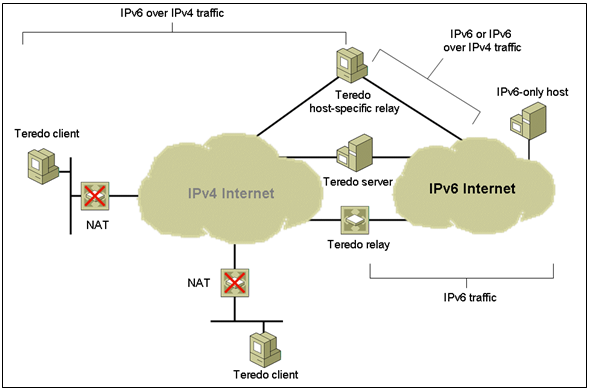
The Teredo infrastructure consists of the following components:
Teredo Clients
A Teredo client is an IPv6/IPv4 node that supports a Teredo tunnelling interface through which packets are tunneled to other Teredo clients or nodes on the IPv6 Internet (via a Teredo relay). A Teredo client communicates with a Teredo server to obtain an address prefix from which a Teredo-based IPv6 address is configured or used to facilitate communication with other Teredo clients or hosts on the IPv6 Internet.
Windows XP with Service Pack 1 (SP1) with the Advanced Networking Pack, Windows XP with Service Pack 2 (SP2), Windows Server 2003 with Service Pack 1 (SP1),Windows Server 2003 with Service Pack 2 (SP2), Windows Vista, and Windows Server 2008 all include the Teredo client.
Teredo Servers
A Teredo server is an IPv6/IPv4 node that is connected to both the IPv4 Internet and the IPv6 Internet, and supports a Teredo tunneling interface over which packets are received. The general role of the Teredo server is to assist in the address configuration of Teredo clients and to facilitate the initial communication between Teredo clients and other Teredo clients or between Teredo clients and IPv6-only hosts. The Teredo server listens on UDP port 3544 for Teredo traffic.
Unlike the client, the Teredo server is not included with Microsoft operating platforms. To facilitate communication between Windows-based Teredo client computers, Microsoft has deployed Teredo servers on the IPv4 Internet.
Teredo Relays
A Teredo relay is an IPv6/IPv4 router that can forward packets between Teredo clients on the IPv4 Internet (using a Teredo tunnelling interface) and IPv6-only hosts. In some cases, the Teredo relay interacts with a Teredo server to facilitate initial communication between Teredo clients and IPv6-only hosts. The Teredo relay listens on UDP port 3544 for Teredo traffic.
Like the Teredo server, Microsoft operating platforms do not include Teredo relay functionality. Microsoft does not currently plan to deploy Teredo relays on the IPv4 Internet. Teredo relays are not required to communicate with Teredo host-specific relays.
Teredo, also known as IPv4 network address translator (NAT) traversal (NAT-T) for IPv6, provides address assignment and host-to-host automatic tunnelling for unicast IPv6 connectivity across the IPv4 Internet, even when the IPv6/IPv4 hosts are located behind one or multiple IPv4 NATs. To traverse IPv4 NATs, IPv6 packets are sent as IPv4-based User Datagram Protocol (UDP) messages
Teredo Host-Specific Relays
Communication between Teredo clients and IPv6 hosts that are configured with a global address must go through a Teredo relay. This is required for IPv6-only hosts connected to the IPv6 Internet. However, when the IPv6 host is IPv6 and IPv4-capable and connected to both the IPv4 Internet and IPv6 Internet, then communication should occur between the Teredo client and the IPv6 host over the IPv4 Internet, rather than having to traverse the IPv6 Internet and go through a Teredo relay.
A Teredo host-specific relay is an IPv6/IPv4 node that has an interface and connectivity to both the IPv4 Internet and the IPv6 Internet and can communicate directly with Teredo clients over the IPv4 Internet, without the need for an intermediate Teredo relay. The connectivity to the IPv4 Internet can be through a public IPv4 address or through a private IPv4 address and a neighboring NAT. The connectivity to the IPv6 Internet can be through a direct connection to the IPv6 Internet or through an IPv6 transition technology such as 6to4, where IPv6 packets are tunneled across the IPv4 Internet. The Teredo host-specific relay listens on UDP port 3544 for Teredo traffic.
Windows XP with SP1 with the Advanced Networking Pack, Windows XP with SP2, Windows Server 2003 with SP1, Windows Server 2003 with SP2, Windows Vista, and Windows Server 2008 include Teredo host-specific relay functionality, which is automatically enabled if the computer has a global address assigned. A global address is assigned in a received Router Advertisement message from a native IPv6 router, an ISATAP router, or a 6to4 router. If the computer does not have a global address, Teredo client functionality is enabled.
The Teredo host-specific relay allows Teredo clients to efficiently communicate with 6to4 hosts, IPv6 hosts with a non-6to4 global prefix, or ISATAP or 6over4 hosts within organizations that use a global prefix for their addresses, provided both hosts are using a version of Windows that supports Teredo
6to4 is an Internet transition mechanism for migrating from IPv4 to IPv6, a system that allows IPv6 packets to be transmitted over an IPv4 network (generally the IPv4 Internet) without the need to configure explicit tunnels. Special relay servers are also in place that allow 6to4 networks to communicate with native IPv6 networks.
6to4 is especially relevant during the initial phases of deployment to full, native IPv6 connectivity, since IPv6 is not required on nodes between the host and the destination. However, it is intended only as a transition mechanism and is not meant to be used permanently.
6to4 may be used by an individual host, or by a local IPv6 network. When used by a host, it must have a global IPv4 address connected, and the host is responsible for encapsulation of outgoing IPv6 packets and decapsulation of incoming 6to4 packets. If the host is configured to forward packets for other clients, often a local network, it is then a router.
Most IPv6 networks use autoconfiguration, which requires the last 64 bits for the host. The first 64 bits are the IPv6 prefix. The first 16 bits of the prefix are always 2002:, the next 32 bits are the IPv4 address, and the last 16 bits of the prefix are available for addressing multiple IPv6 subnets behind the same 6to4 router. Since the IPv6 hosts using autoconfiguration already have determined the unique 64 bit host portion of their address, they must simply wait for a Router Advertisement indicating the first 64 bits of prefix to have a complete IPv6 address. A 6to4 router will know to send an encapsulated packet directly over IPv4 if the first 16 bits are 2002, using the next 32 as the destination, or otherwise send the packet to a well-known relay server, which has access to native IPv6.
6to4 does not facilitate interoperation between IPv4-only hosts and IPv6-only hosts. 6to4 is simply a transparent mechanism used as a transport layer between IPv6 nodes
6to4 performs three functions:
- Assigns a block of IPv6 address space to any host or network that has a global IPv4 address.
- Encapsulates IPv6 packets inside IPv4 packets for transmission over an IPv4 network using 6in4.
- Routes traffic between 6to4 and “native” IPv6 networks
Address block allocation
For any 32-bit global IPv4 address that is assigned to a host, a 48-bit 6to4 IPv6 prefix can be constructed for use by that host (and if applicable the network behind it) by appending the IPv4 address to 2002::/16.
For example the global IPv4 address 192.0.2.4 has the corresponding 6to4 prefix 2002:c000:0204::/48. This gives a prefix length of 48 bits, which leaves room for a 16-bit subnet field and 64 bit host addresses within the subnets.
Any IPv6 address that begins with the 2002::/16 prefix (in other words, any address with the first two octets of 2002 hexadecimal) is known as a 6to4 address, as opposed to a native IPv6 address which does not use transition technologies.
Encapsulation and transmission
6to4 embeds an IPv6 packet in the payload portion of an IPv4 packet with protocol type 41. To send an IPv6 packet over an IPv4 network to a 6to4 destination address, an IPv4 header with protocol type 41 is prepended to the IPv6 packet. The IPv4 destination address for the prepended packet header is derived from the IPv6 destination address of the inner packet (which is in the format of a 6to4 address), by extracting the 32 bits immediately following the IPv6 destination address’ 2002::/16 prefix. The IPv4 source address in the prepended packet header is the IPv4 address of the host or router which is sending the packet over IPv4. The resulting IPv4 packet is then routed to its IPv4 destination address just like any other IPv4 packet.
Routing between 6to4 and native IPv6

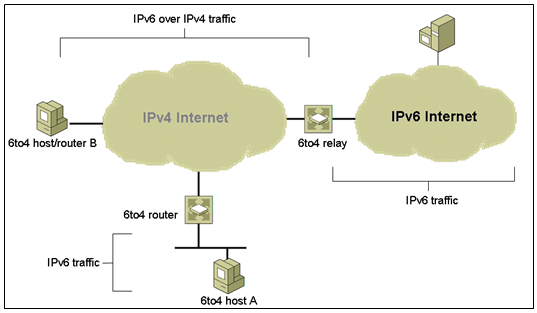
The figure depicts two isolated 6to4 networks, Site A and Site B. Each site has configured a router with an external connection to an IPv4 network. In the figure, a 6to4 tunnel across the IPv4 network connects the 6to4 sites.
Before an IPv6 site can become a 6to4 site, you must configure at least one router interface for 6to4 support. This interface must provide the external connection to the IPv4 network. The address that you configure on qfe0 must be globally unique. In the previous figure, boundary Router A’s interface qfe0 connects Site A to the IPv4 network. Interface qfe0 must already be configured with an IPv4 address before you can configure qfe0 as a 6to4 pseudo-interface.
In the figure, 6to4 Site A is composed of two subnets, which are connected to interfaces hme0 and hme1 on Router A. All IPv6 hosts on either subnet of Site A automatically reconfigure with 6to4–derived addresses on receipt of the advertisement from Router A.
Site B is the opposite endpoint of the tunnel from Site A. To correctly receive traffic from Site A, a boundary router on Site B must be configured for 6to4 support. Otherwise, packets that the router receives from Site A are not recognized and dropped.
To allow hosts and networks using 6to4 addresses to exchange traffic with hosts using “native” IPv6 addresses, “relay routers” have been established. A relay router connects to an IPv4 network and an IPv6 network. 6to4 packets arriving on an IPv4 interface will have their IPv6 payloads routed to the IPv6 network, while packets arriving on the IPv6 interface with a destination address prefix of 2002::/16 will be encapsulated and forwarded over the IPv4 network.
There is a difference between a “relay router” and a “border router” (also known as a “6to4 border router”). A 6to4 border router is an IPv6 router supporting a 6to4 pseudo-interface. It is normally the border router between an IPv6 site and a wide-area IPv4 network, where the IPv6 site uses 2002::/16 co-related to the IPv4 address used later on. On the other hand, a “relay router” is a 6to4 router configured to support transit routing between 6to4 addresses and pure native IPv6 addresses.
To allow a 6to4 host to communicate with the native IPv6 Internet, it must have its IPv6 default gateway set to a 6to4 address which contains the IPv4 address of a 6to4 relay router. To avoid the need for users to set this up manually, the anycast address of 192.88.99.1 has been allocated for the purpose of sending packets to a 6to4 relay router. Note that when wrapped in 6to4 with the subnet and hosts fields set to zero this IPv4 address (192.88.99.1) becomes the IPv6 address 2002:c058:6301::. To ensure BGP routing propagation, a short prefix of 192.88.99.0/24 has been allocated for routes pointed at 6to4 relay routers that use this anycast IP address. Providers willing to provide 6to4 service to their clients or peers should advertise the anycast prefix like any other IP prefix, and route the prefix to their 6to4 relay.
Packets from the IPv6 Internet to 6to4 systems must be sent to a 6to4 relay router by normal IPv6 routing methods. The specification states that such relay routers must only advertise 2002::/16 and not subdivisions of it to prevent IPv4 routes polluting the routing tables of IPv6 routers. From here they can then be sent over the IPv4 Internet to the destination.
For a 6to4 host to have fast and reliable connectivity with a host natively using the IPv6 Internet, both the 6to4 host and the native IPv6 host must have a route to a fast, reliable and correctly configured relay server. The 6to4 host’s ISP can ensure that outgoing packets go to such a relay, but they have no control over the relay used for the responses from the native IPv6 host. A variant called IPv6 rapid deployment (“6rd”) uses the same basic principles as 6to4 but uses a relay operated by the 6rd user’s ISP for traffic in both directions. To achieve this an address block allocated by the user’s ISP is used instead of 2002::/16.
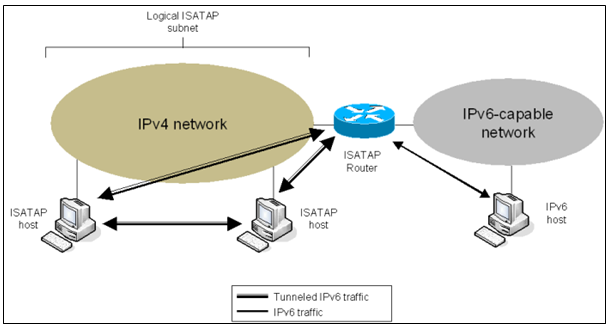
ISATAP (Intra-Site Automatic Tunnel Addressing Protocol) is an IPv6 transition mechanism meant to transmit IPv6 packets between dual-stack nodes on top of an IPv4 network. ISATAP defines a method for generating a link-local IPv6 address from an IPv4 address, and a mechanism to perform Neighbour Discovery on top of IPv4.
Its impact on your IPv4 support infrastructure is reduced to the configuration of one ISATAP router. With ISATAP, IPv4-dependent applications continue to utilize IPv4 while newer IPv6-capable applications can be deployed immediately. Both types of traffic will share a single common IPv4 infrastructure. ISATAP-based connectivity can immediately be used to deliver IPv6 services while the IPv4-only infrastructure is gradually migrated to integrate native IPv6 capabilities.
Link-local address generation
Any host wishing to participate in ISATAP over a given IPv4 network can set up a virtual IPv6 network interface. The link-local address is determined by prepending fe80::0200:5efe:… for globally unique addresses, or fe80::0000:5efe:… for private addresses, in front of the 32 bits of the host’s IPv4 address.
For example, the global IPv4 address 192.0.2.143 would use fe80::0200:5efe:192.0.2.143 as its link-local IPv6 address. The shortened notation would be fe80::200:5efe:c000:028f (where c0 00 02 8f is 192.0.2.143 in hexadecimal notation)
The benefits of ISATAP are the following:
- An existing IPv4 infrastructure can provide unicast IPv6 connectivity immediately with the only requirement being the configuration of an ISATAP router. Native IPv6 capabilities can be enabled slowly over time during natural refresh cycles.
- Native IPv6 connectivity can be enabled first in the backbone, while allowing other parts of the IPv4 infrastructure to preserve their investment and naturally evolve to support native IPv6. ISATAP islands can be created to allow gradual evolution to native IPv6 capabilities within different parts of an organization without blocking end-to-end IPv6 service deployments.
- End-to-end IPv6 services can be enabled and maintained using ISATAP while allowing access to native IPv6 infrastructure, such as a native IPv6 backbone or the IPv6 Internet.
Useful Links
http://technet.microsoft.com/en-us/library/bb962076.aspx#ID0ETGAC
Microsoft Document showing much greater detail on Teredo, 6to4 and ISATAP


