Kubenetes components
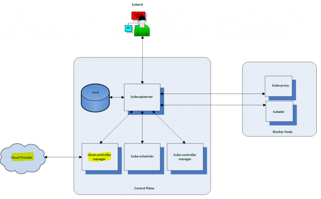
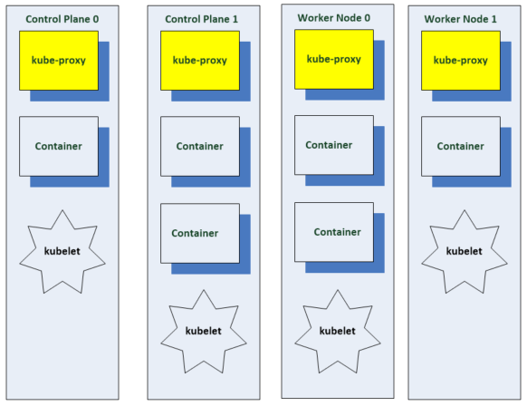
As seen in the diagram below, every Kubernetes cluster will have one or more control plane nodes and one more worker nodes. The Control Plane manages the worker nodes and the Pods in the cluster. The worker nodes host the pods that are the components of the application workload. There are no Cloud Providers if this is running on bare metal.
Components running on the control plane node include
- etcd is the persistent datastore for Kubenetes which stores the cluster state.
- kube-api-server is the front end for the Kubernetes control plane which exposes the Kubernetes API and the only component which accesses the etcd.
- kube-scheduler assigns workloads to the worker nodes and decides which nodes pods will be run on.
- The kube-controller manager runs a collection of control processes to manage various resources. It monitors when nodes go down, maintains the correct number of pods, joins services and pods and creates default accounts and API access tokens for new namespaces.
- The cloud controller manager runs controllers which provision underlying infrastructure needed by workloads. It has a control loop to manage storage volumes if a workload needs persistent storage.
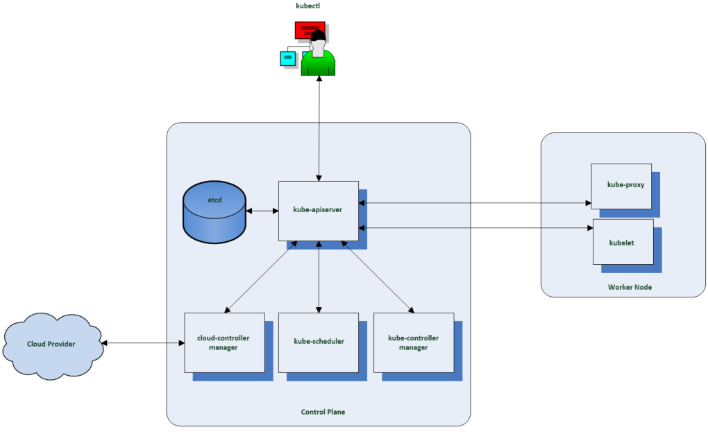
Components run on a worker node
- Kubelet – Primary node agent which is responsible for spinning up containerized workloads that are assigned to its node.
- Kube Proxy – Used for implementing Kubenetes services such as network components which connect workloads in the cluster.
- A container runtime such as Docker
etcd
etcd is the database for Kubernetes. It is a distributed key value store. etcd clusters can be 3 or 5 nodes and each node has a copy of the datastore providing fault tolerance.
To maintain consensus, it uses an algorithm called Raft. The nodes can connect to each other on port 2380. To establish consensus they must maintain quorum which requires more than half the nodes in the cluster to be available. If Quorum is lost, the cluster cannot reach consensus and cannot process changes.
3 nodes can tolerate the loss of 1 node.
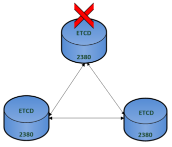
5 nodes can tolerate the loss of 2 nodes.
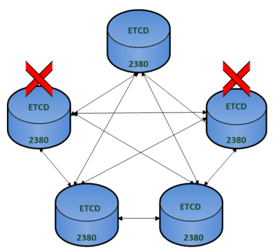
The diagram below shows the etcd members in their own dedicated cluster. The etcd client which is the Kubenetes API server connects to any of the members on port 2380.
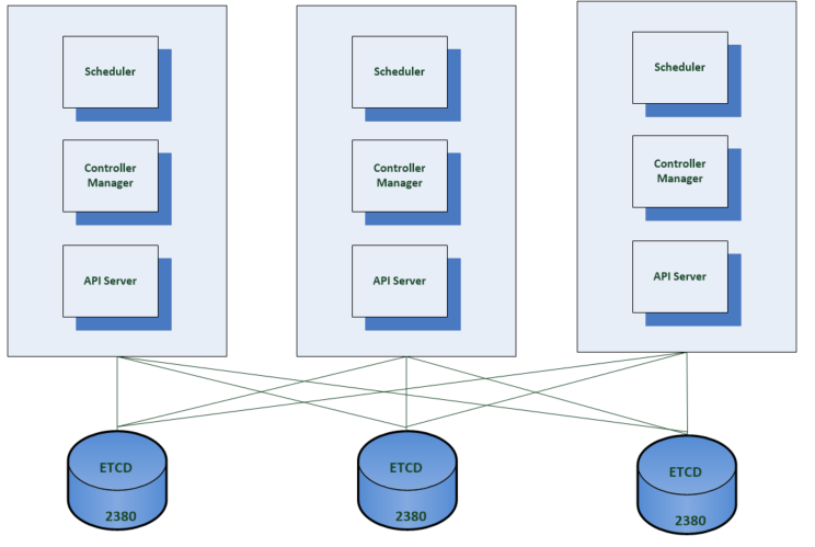
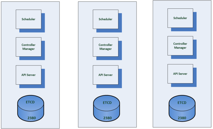
Alternatively the etcd members can be located with the control plane components on the same machine. The location will depend on cost, performance and capacity. It is not recommended to share the etcd cluster for the Kubernetes cluster with other applications and worth dedicating an etcd installation to the Kubernetes cluster.
Using the Kubernetes command-line tool to find information
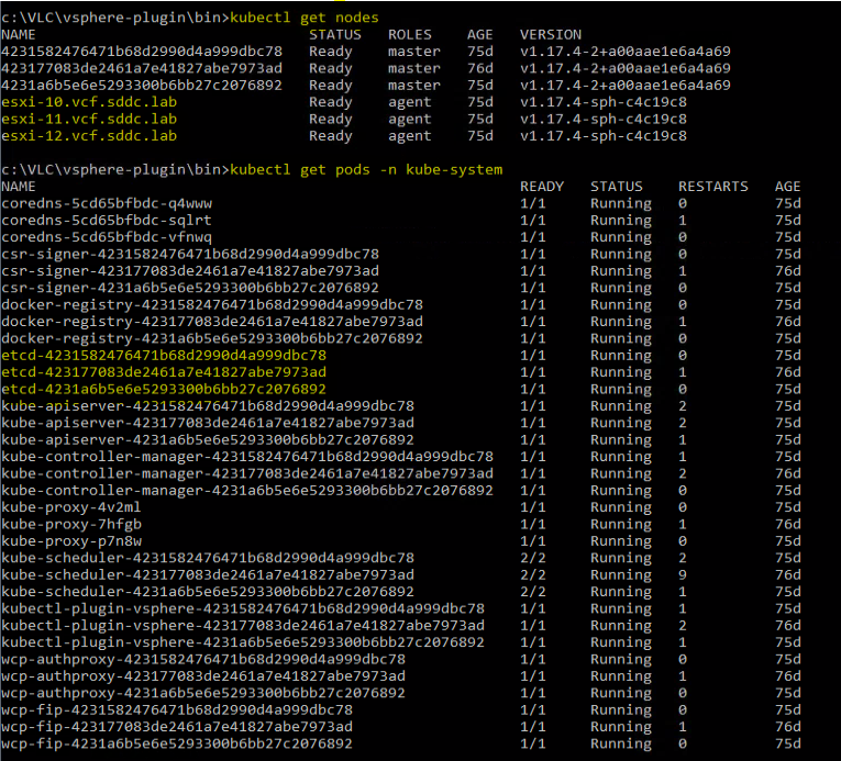
If we run the command get-nodes, we can see the 3 control nodes
If we run the command get pods -n kube-system , then we can see the 3 etcd pods that are running on the control plane nodes in a co-located config.
Kubenetes API Server
The API server is where all control plane operations are exposed to the API. We use a tool called kubectl which translates commands into http rest style API calls.
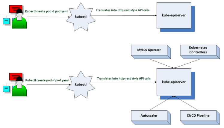
Custom resource definitions
Kubernetes is extensible via custom resource definitions. CRDs are used to create our own API types.
Once we create a CRD in Kubernetes we can use it like any other native Kubernetes object thus leveraging all the features of Kubernetes
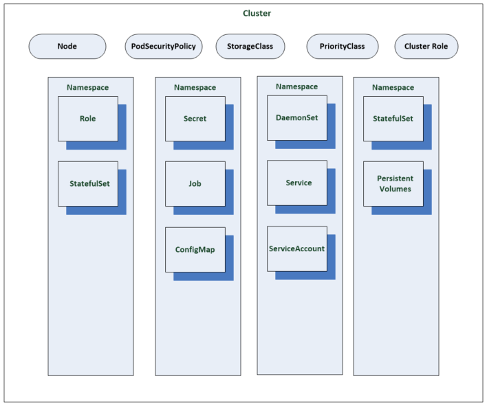
Kubenetes API resources
All components communicate with the API server. The API server’s REST endpoint implements the open API specification. Objects created in the API are implementations of Kubernetes resources
Resources include Pods, Services and Namespaces. Each resource contains a spec which defines the desired state of the resource and a status which includes the current state of the object in the system.
Resources can come under a cluster or namespace scope depending on their implementation. You can see below how some resources fit into each category.
API versioning
There are several meanings in Kubernetes
Alpha level
- Could contain bugs
- May be disabled by default
- Lack of support
Beta Level
- Tested
- Enabled by default
- Supported for a length of time to enable adoption and use
- Details may change
GA Level
- Stable
- Will be available through several versions
- Details are set
Authentication and Authorization
kubectl is used by parsing a local configuration file containing authentication data and data about the request and posting that json data to the API endpoint. The API server then answers requests from the controllers.
Firstly, the API server needs to authenticate that you are allowed to make a request using different methods of configuration authentication. Kubernetes doesn’t have a concept of a user object and doesn’t store user details. It uses authenticators for this task which are configured by the administrators.
For authorization, the API leverages authorizers and authorization policies. To view these, you can type kubectl auth can-i –list to list the resources, the resource URLs and the verbs you can use within a cluster.
Admission control comes after authorization. we can then validate or mutate the request. Validation just checks the validation logic and makes sure it is correct. Mutate will looks at an object and potentially change that object.
The API server then does some spec validations. These are validation routines and check that everything in your spec is correct and notify you on typos and format errors.
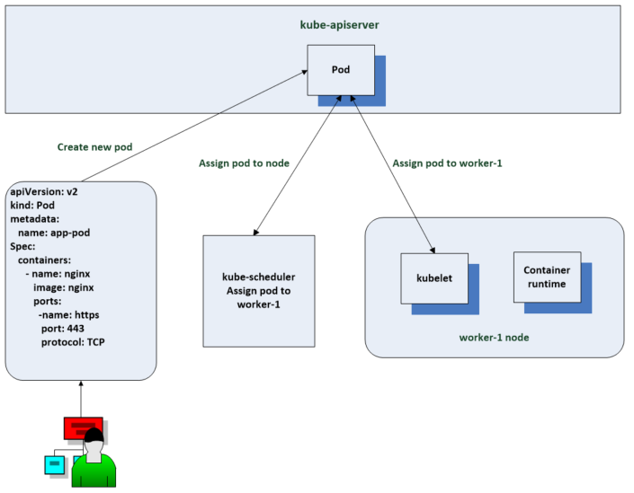
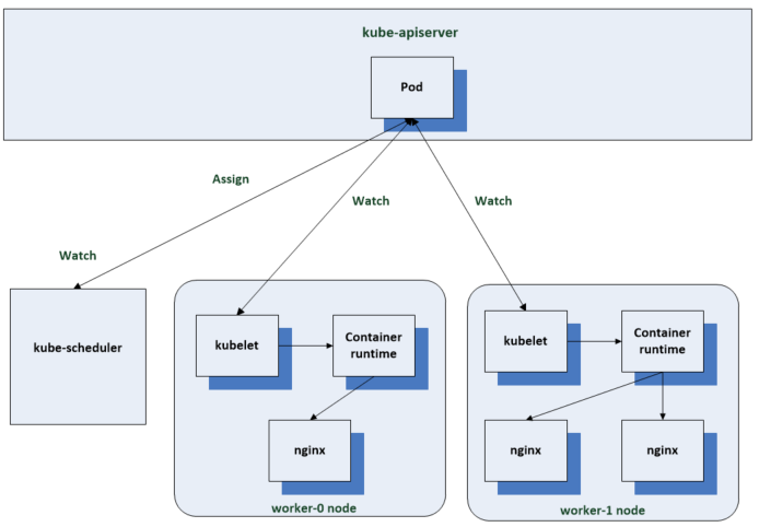
Scheduler
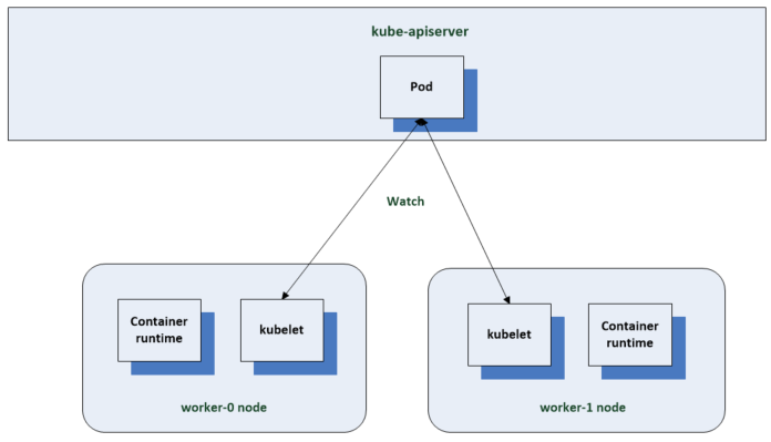
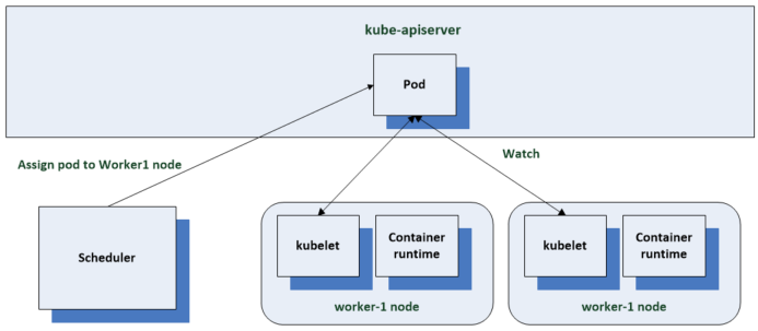
The scheduler’s job is to assign pods to nodes. When you create a pod request, you will provide the pods name and image that it will use. You don’t have to define a node for the pod but the option is there. The scheduler watches for new pod resources to be created. This watch functionality is exposed by the api servers to the controllers and the scheduler uses it to watch pods. When the scheduler finds one that doesn’t have a node name field set, it determines where the pod should run and updates the pod resource in the node name field to add a value to the field. The kubelet on the assigned node will then change the current state to the defined desired state.
The scheduler goes through a process of filtering and scoring stages. Filtering comes first and filters out any nodes which cannot host a pod. There may be something called a taint on the node which describes something a node cannot tolerate and if this isn’t written in the manifest then the node cannot host the pod. However, if the information is written in the manifest, then it will be able to.
A pod may request a certain amount of RAM and CPU or have a requirement for a GPU for example.
Once the filtering is complete, it moves on to the scoring stage. Scoring the candidates means finding the best host for scheduling the pod. Some pods will have an affinity section which sets a preference for scheduling a pod in a certain zone. Another scoring factor could be whether the node has the container image being used by the pod. Also lower workload utilisation on a node may give a preference.
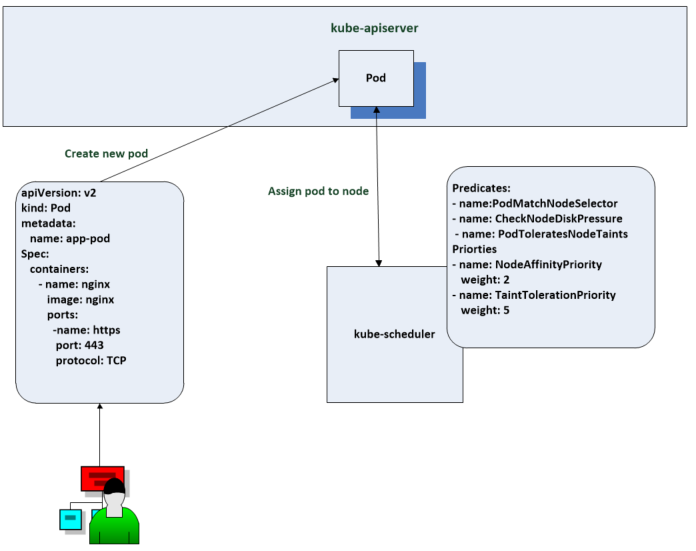
Customised scheduling – Policies and Profiles
You can configure the behaviour of the default scheduler using policies and profiles using predicates (used for filtering) and priorities (used for scoring)
You can also build your own scheduler with custom scheduling logic instead of the existing scheduler.
Running more than one scheduler
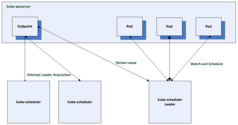
The scheduler should be run in a highly available configuration at all times however, only one scheduler is active at any one time.
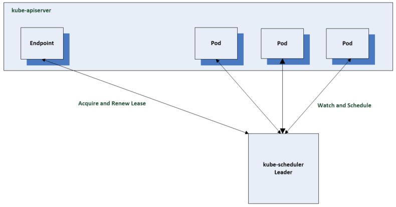
The first scheduler will acquire a leader lease using an endpoint by default to record a leader lease. The other schedulers will be online and fail to acquire the leader lease. They will periodically it check the lease is current for the active leader and will succeed if the leader is unavailable
The Kube Controller Manager
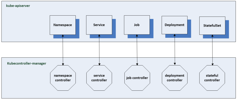
The Kube Controller Manager runs the core control loops for the Kubernetes control plane. There are many different controllers. Several are responsible for maintaining the desired state of common resources in a Kubernetes cluster. Each controller has a specific set of functionality which depend on the resource they manage.
A control loop is a non terminating loop which regulates the state of the system. In Kubernetes, a controller is a control loop that watches the shared state of the cluster through the API server and makes changes to move the current state towards the desired state.
A controller is responsible for managing a resource and it will have a watch on the resource kind for which it is responsible. The watch is a continuous connection with the kube-api server where notification of changes is sent to the controller. It will then work on changing the existing state to the desired state. It will try to continue trying if it can’t finish the first time.
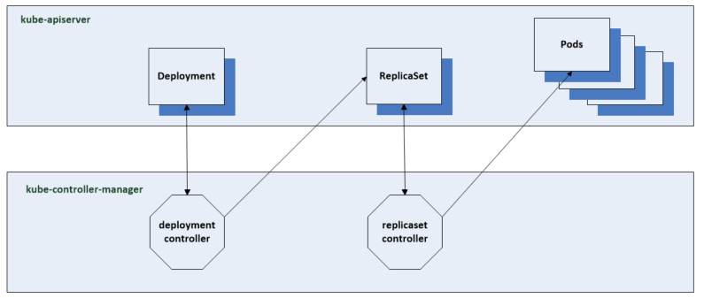
If a replica set is created then we are duplicating pods. If we want 4 replicas as our desired state. the scheduler will start assigning these replica sets to nodes. A deployment controller will create these replica sets.
Like the scheduler, when used in a highly available configuration, the controller manager uses a leader election to ensure only one instance is actively managing resources in a cluster at a time.
Cloud Controller Manager
The cloud controller manager is similar to the kube controller manager. It is a collection of controllers with the same principles around control loops and leader elections. The Cloud Controller Manager will not be found in every cluster if you’re running on bare metal. The cloud controller manager lets you link your cluster into your cloud provider’s API and separates out the components that interact with that cloud platform from components that just interact with your cluster.
Controllers inside the Cloud controller manager
- Node Controller: The node controller is responsible for creating node objects when new servers are created in your cloud infrastructure. The node controller obtains information about the hosts running inside your tenancy with the cloud provider.
- Route controller: The route controller is responsible for configuring routes in the cloud correctly so that containers on different nodes in your Kubernetes cluster can communicate.
- Service Controller: Services integrate with cloud infrastructure components such as managed load balancers, IP addresses, network packet filtering, and target health checking. The service controller interacts with your cloud provider’s APIs to set up load balancers and other infrastructure components.
Examples
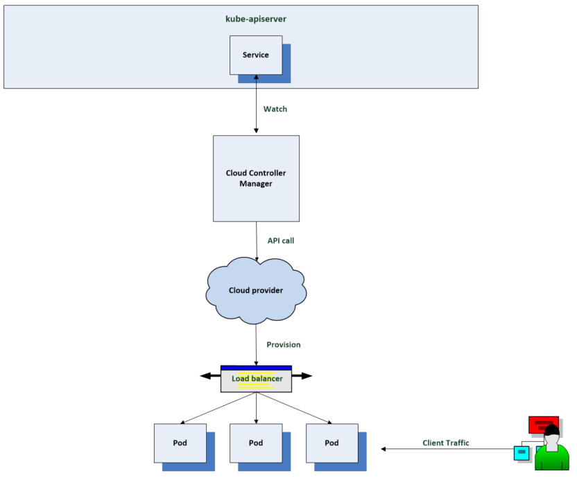
If you have a workload that you would like to expose to requests from outside, one way to do this is to put it behind a Kubernetes service such as a load balancer. If you have a cloud controller manager set up, it will configure a load balancer through your cloud providers API and configure it to route traffic to the pods for your workload.
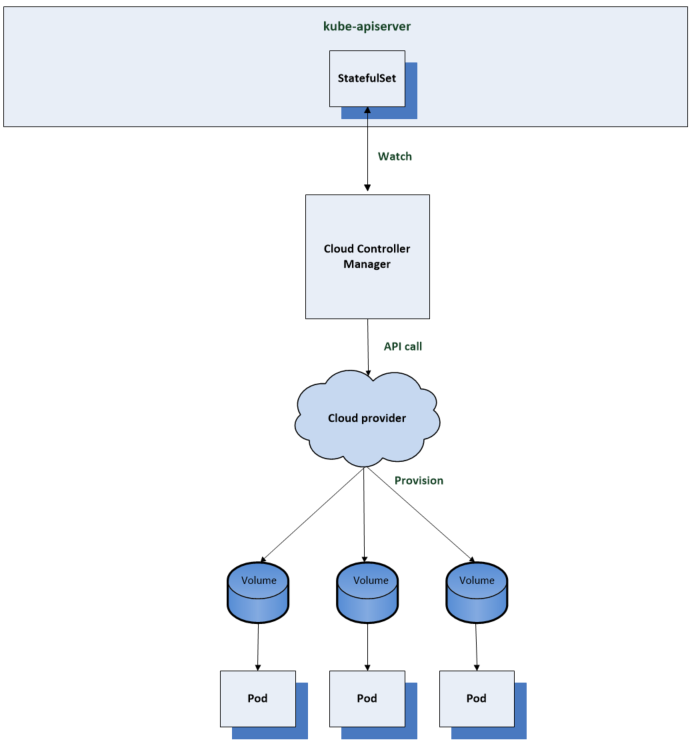
Another example could be a workload which requires persistent storage. You can set up storage classes which leverage a provisioner from a cloud provider. This allows you to provision backing storage volumes for your workload on demand for example by referencing a storage class from a Kubernetes stateful set. The cloud controller manager will use the cloud providers API to provision the storage volumes when needed so they can be mounted in a workloads pod.
Kubelet
The kubelet is the primary Kubernetes node agent. It runs on every node in the cluster. It’s responsible for running the containers for the pods which are scheduled to its node. The kubelet for each node keeps a watch on pod resources in the api server.
The kubelet is another Kubernetes controller which provides an interface between the Kubernetes control plane and the container runtime on each server in the cluster.
Whenever the scheduler assigns a pod to a node in the api server, the kubelet for that node reads the pod spec then instructs the container runtime to spin up the container to build that spec. The container runtime then downloads the container images if they’re not there, then starts the container. The kubelet instructs the container runtime using the container runtime interface or CRI.
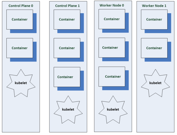
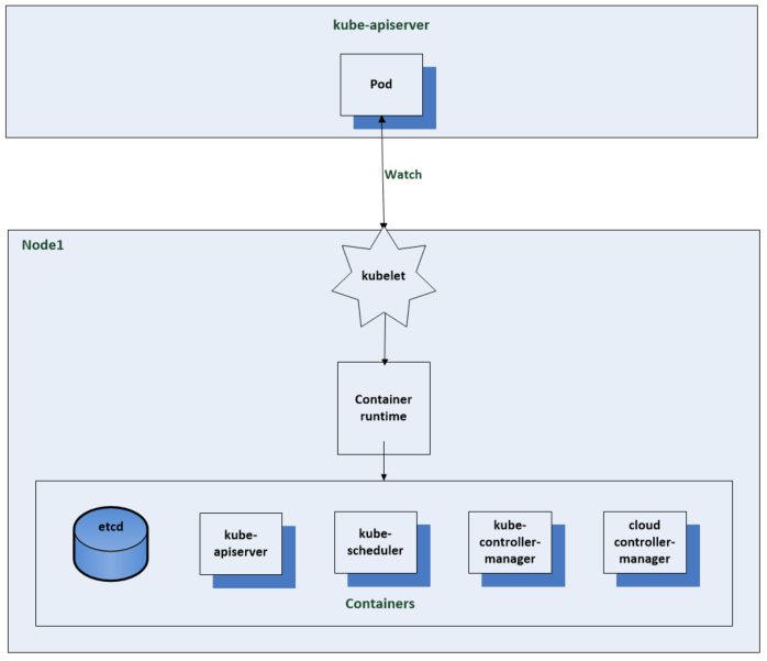
The kubelet is the only Kubernetes component that does not run in a container. The kubelet along with the container runtime are installed and run directly on the machine that is the node in the cluster.
The other components are typically run in containers as kubernets pods but this is the general convention below
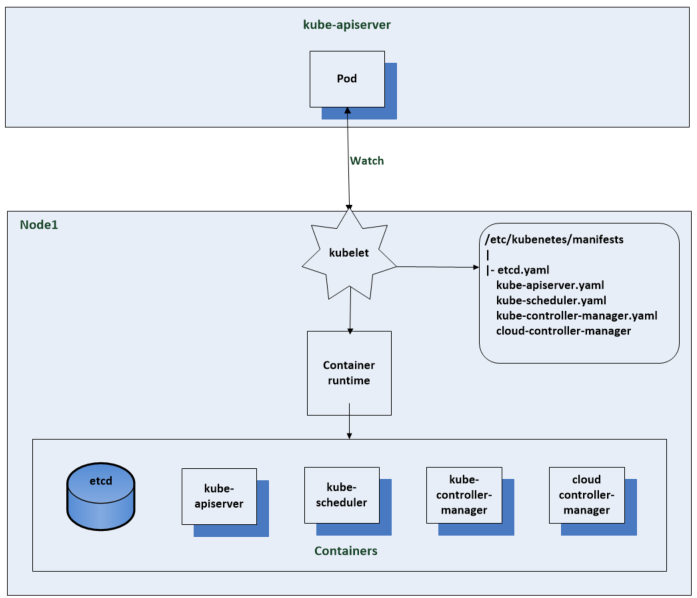
The Kubelet gets notifications from the api server on what pods to run. The api server and other control plane components get created by using static pod manifests. When you start the kubelet you can set a path to the directory or file that contains these static pod manifests. The kublelet tells the container runtime to spin up the containers for the pod manifests and monitor them for changes. It can also make http requests to remote endpoints or listen for http connections to get to pod manifests but the most common method is to do static pod manifests on a local file system seen below.
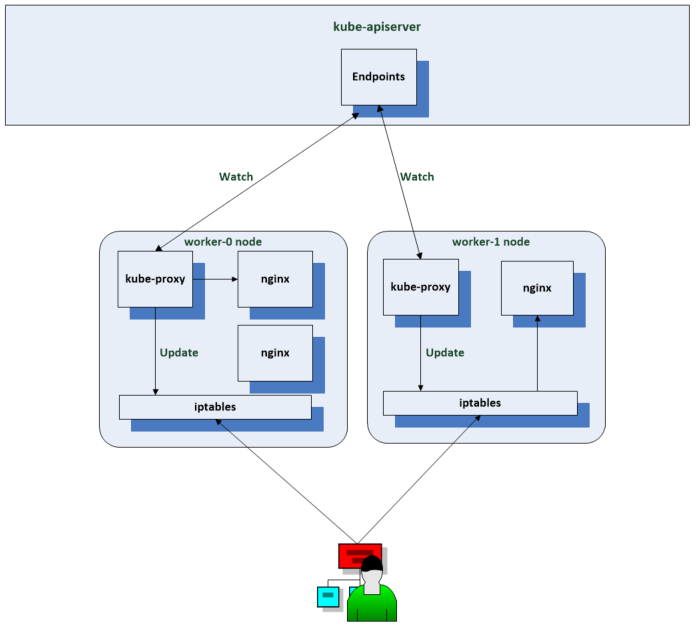
Kube Proxy
Similar to the kubelet the kube proxy runs on every node in the cluster. Unlike the kubelet the kube proxy runs in a Kubernetes pod
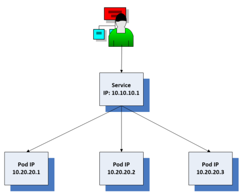
kube-proxy enables essential functionality for Kubernetes services. If services didn’t exist then when a client application needed to connect to server pods in a cluster then it would need to use the pods IP to connect to the pod on the IP network. It would need to retrieve and maintain a list of all the pod addresses which is unnecessary work. In Kubernetes it is likely that pods will be created and destroyed frequently so we need a better way to manage it. The service provides a stable IP address seen here as 10.10.10.1.
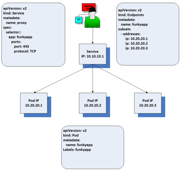
A controller keeps track of the pods associated with the service and adds and removes them from the back end pool as needed. The client just needs the address of the service and the rest is taken care of by the end point resource which is usually created on your behalf by a controller. If you create a service with a sector which references a label applied to the pods, the endpoints resource is created for you. There the addresses for the back end pods are maintained. If the pool of pods changes, the endpoints will be updated and the client requests routed appropriately. It looks like this service is a proxy, that load balances requests to the back end but in Kubernetes applications, it works slightly differently
We have a end point controller in the kube controller manager that manages the end point resources. It manages the associations between services and pods. Each node in the cluster has the kube proxy running and watching service and end point service resources. When a change occurs which needs updating, kube proxy updates rules in ip tables which is a network packet filtering utility which allows network rules to be set in the network stack of the Linux kernel. kube proxy offers alternatives to using ip tables but this is the most common option.
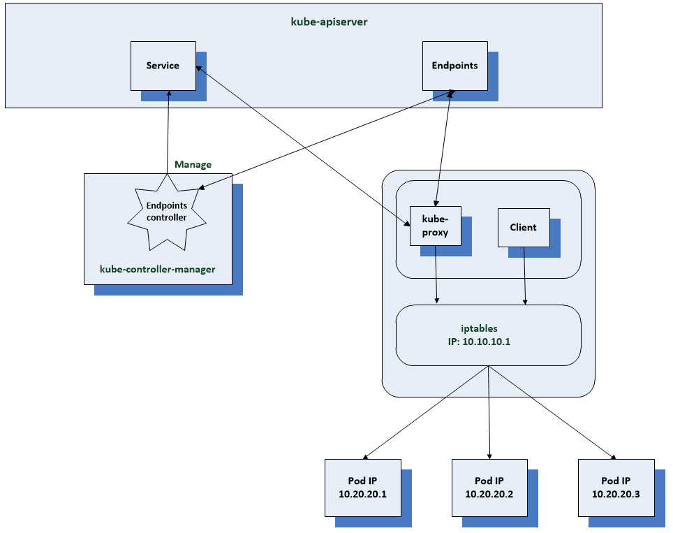
Now when a client pod sends a request to the services IP, it gets routed by the kernel to one of the pod IPs depending on the rule which has been set by kube proxy. When using IP tables the pod selected by the pool will be random. For more control you would have to use IPVS (IP Virtual Server) which implements layer 4 load balancing in the Linux kernel.
The services IP is a virtual IP and you won’t get a response if you ping it. It is essentially a key in the rule set by IP tables which gives network packet routing instructions to the host’s kernel. The client pod can use the service IP like it normally would as like it was calling an actual pod IP.
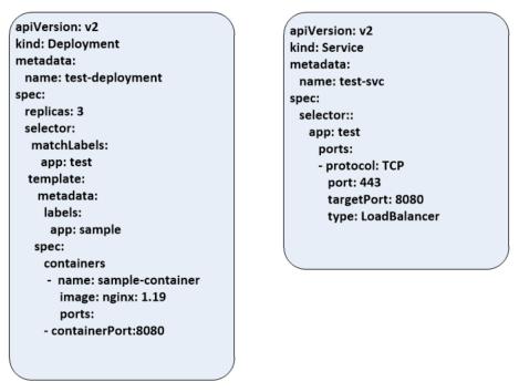
Sample manifests
The below screenprints shows a sample manifest for a deployment and service resources
The deployment manifest shows the name of test-deployment with 3 replica pods in the deployment. The selector indicates that this deployment will manage pods with the label app: test and in the template we give that label to the pods. Each pod will consist of a single container with the same sample-container and run the nginx container image and listen on port 8080. It will also spin up a load balancer with the cloud provider to expose it to requests from outside the cluster.
kubectl appy -f deployment.yaml -f service.yaml
This command above will translate the command into a REST API call to the Kubernetes API server. The API server will authenticate and authorize the user and then apply any admission control operations such as pod security policies. if it fails the resource will not be created
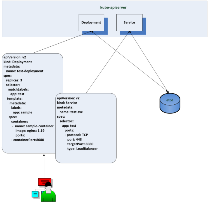
Once this is complete the various controllers in the system are notified by the watch mechanism and work to change the existing state to the desired state.
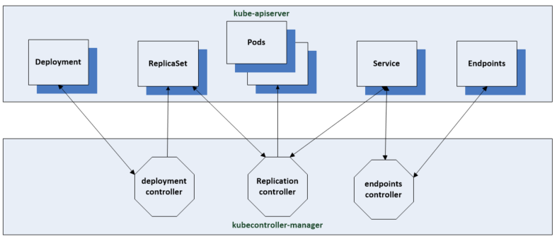
- The Deployment controller creates the corresponding replica set with the 3 replicas which were defined in the manifest
- The Replication controller is notified of the new replica sets and in response creates the 3 separate pod resources using the pod template
- The Endpoints controller will create the endpoints resource which connects the individual pods to the service by the pods label
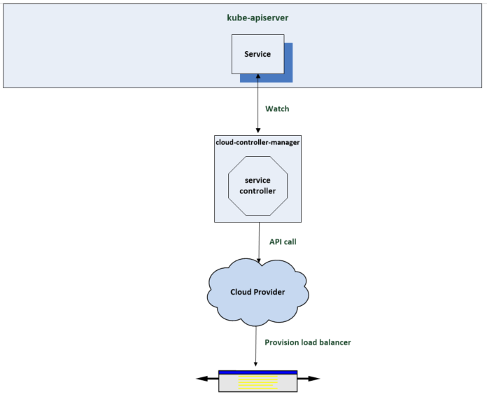
Another controller which is notified in response to the resources being created is the service controller. The previous controllers are part of the core Kubernetes controllers in the kube controller manager. This controller is part of the cloud controller manager which is responsible for integrations with the underlying cloud providing infrastructure. The service controller is notified by its watch when the services resource is created. It notices that the spec includes a load balancer and responds by calling the cloud providers api to have a load balancer provisioned to route traffic to the cluster and associated pods.
Next the scheduler is watching for new pods and when the replication controller creates them, the scheduler is notified and responds by finding worker nodes for the containers to run on to fulfil the pod spec. Once the assignments have been made, the next controller which is the kubelet instructs the local container runtime to create the requested container image from the nginx deploy spec manifest.
Now the containers are up and running we have to get network access to these containers and this is what kube proxy is used for. It watches the endpoints resource which connects the service to the pod and updates IP tables on it nodes to ensure that traffic sent to the services ip gets routed to one of the pod IPs. This includes any client request from outside the cluster, inside the cluster and through the cloud providers load balancer.