VLANs provide for logical groupings of stations or switch ports, allowing communications as if all stations or ports were on the same physical LAN segment. Confining broadcast traffic to a subset of the switch ports or end users saves significant amounts of network bandwidth and processor time.
In order to support VLANs for VMware Infrastructure users, one of the elements on the virtual or physical network has to tag the Ethernet frames with 802.1Q tag as per below
The most common tagging is 802.1Q, which is an IEEE standard that nearly all switches support. The tag is there to identify which VLAN the layer 2 frame belongs to. vSphere can both understand these tags (receive them) as well as add them to outbound traffic (send them)

There are three different configuration modes to tag (and untag) the packets for virtual machine frames
- VST (VLAN range 1-4094)
- VGT (VLAN ID 4095 enables trunking on port group)
- EST (VLAN ID 0 Disables VLAN tagging on port group)
1. VST (Virtual Switch Tagging)
This is the most common configuration. In this mode, you provision one port group on a virtual switch for each VLAN, then attach the virtual machine’s virtual adapter to the port group instead of the virtual switch directly.
The virtual switch port group tags all outbound frames and removes tags for all inbound frames. It also ensures that frames on one VLAN do not leak into a different VLAN.
Use of this mode requires that the physical switch provide a trunk. E.g The ESX host network adapters must be connected to trunk ports on the physical switch.
The port groups connected to the virtual switch must have an appropriate VLAN ID specified
switchport trunk encapsulation dot1q
switchport mode trunk
switchport trunk allowed vlan x,y,z
spanning-tree portfast trunk
Note: The Native VLAN is not tagged and thus requires no VLAN ID to be set on the ESX/ESXi portgroup.
2. VGT (Virtual Guest Tagging)
You may install an 802.1Q VLAN trunking driver inside the virtual machine, and tags will be preserved between the virtual machine networking stack and external switch when frames are passed from or to virtual switches. Use of this mode requires that the physical switch provide a trunk
3. EST (External Switch Tagging)
You may use external switches for VLAN tagging. This is similar to a physical network, and VLAN configuration is normally transparent to each individual physical server.
There is no need to provide a trunk in these environments.
All VLAN tagging of packets is performed on the physical switch.
ESX host network adapters are connected to access ports on the physical switch.
The portgroups connected to the virtual switch must have their VLAN ID set to 0.
See this example snippet of a code from a Cisco switch port configuration:
switchport mode access
switchport access vlan x
Virtual Distributed Switches
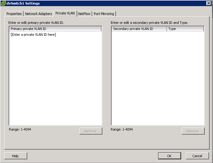
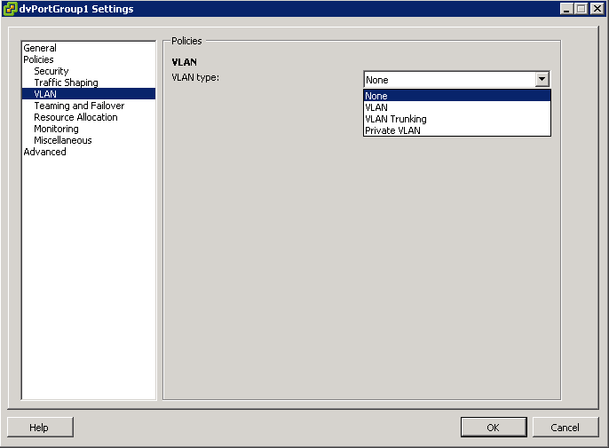
In vSphere, there’s a new networking feature which can be configured on the distributed virtual switch (or DVS). In VI3 it is only possible to add one VLAN to a specific port group in the vSwitch. in the DVS, you can add a range of VLANs to a single port group. The feature is called VLAN trunking and it can be configured when you add a new port group. There you have the option to define a VLAN type, which can be one of the following:
- None
- VLAN
- VLAN trunking
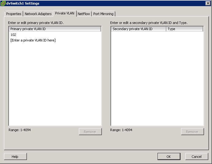
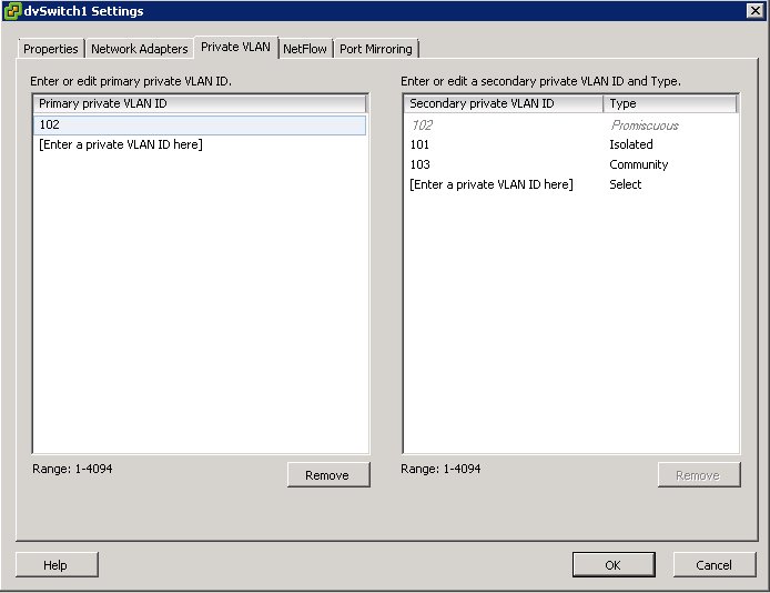
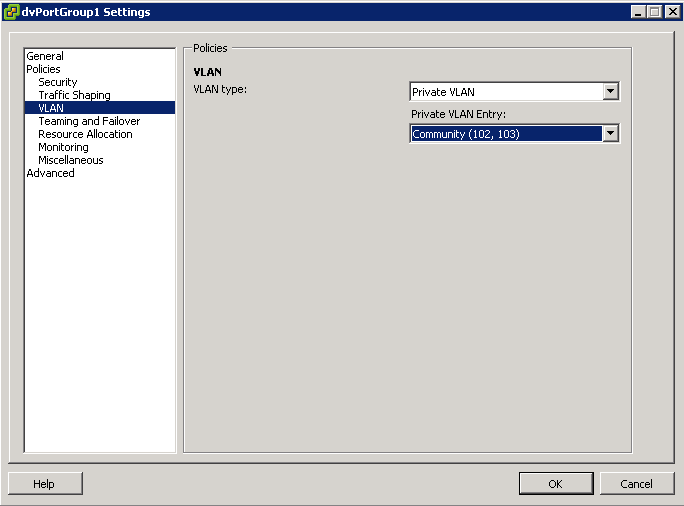
- Private VLAN. But this can only be done on the DVS, not on a regular vSwitch. See screendumps below (both from vSphere environment)
The VLAN policy allows virtual networks to join physical VLANs.
- Log in to the vSphere Client and select the Networking inventory view.
- Select the vSphere distributed switch in the inventory pane.
- On the Ports tab, right-click the port to modify and select Edit Settings.
- Click Policies.
- Select the VLAN Type to use.
- Select VLAN Trunking
- Select a VLAN ID between 1- 4094
- Note: Do not use VLAN ID 4095

What is a VLAN Trunk?
A VLAN trunk is a port on a physical switch that has the ability to listen and pass traffic for multiple VLANs. Trunks are used primarily to pass traffic between multiple switches.
In Cisco networks, trunking is a special function that can be assigned to a port, making that port capable of carrying traffic for any or all of the VLANs accessible by a particular switch. Such a port is called a trunk port, in contrast to an access port, which carries traffic only to and from the specific VLAN assigned to it. A trunk port marks frames with special identifying tags (either ISL tags or 802.1Q tags) as they pass between switches, so each frame can be routed to its intended VLAN. An access port does not provide such tags, because the VLAN for it is pre-assigned, and identifying markers are therefore unnecessary.
A quick note on the relationship between VLANs and vSwitch port groups. A VLAN can contain multiple port groups, but a port group can only be associated with one VLAN at any given time. A prerequisite for VLAN functionality on a vSwitch (vSS or vDS) is that the vSwitch uplinks must be connected to a trunk port on the physical switch. This trunk port will also need to include the associated VLAN ID range, enabling the physical switch to pass VLAN tags to the ESXi host. So why is any of this important? A trunk port can store and distribute multiple VLAN tags, enabling multiple traffic types to flow independently (at least logically), across the same uplink or group of uplinks in the case of teamed NICs
Use case for using VLAN trunking would be if you have multiple VLANs in place for logical separation or to isolate your VM traffic but you have a limited amount of physical uplink ports dedicated for your ESXi hosts
Networking Policies
Policies set at the standard switch or distributed port group level apply to all of the port groups on the standard switch or to ports in the distributed port group. The exceptions are the configuration options that are overridden at the standard port group or distributed port level.
- Load Balancing and Failover Policy
- VLAN Policy
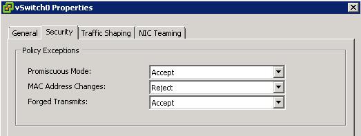
- Security Policy
- Traffic Shaping Policy
- Resource Allocation Policy
- Monitoring Policy
- Port Blocking Policies
- Manage Policies for Multiple Port Groups on a vSphere Distributed Switch
Useful Post (Thanks to Mohammed Raffic)
http://www.vmwarearena.com/2012/07/vlan-tagging-vst-est-vgt-on-vmware.html?goback=.gde_42087_member_239011765