Alongside its operating systems, Microsoft offers the Security Support Provider Interface (SSPI) which is the foundation for Windows authentication. The SSPI provides a universal, industry-standard interface for secure distributed applications. SSPI is the implementation of the Generic Security Service API (GSSAPI) in Windows Server operating systems. For more information about GSSAPI, see RFC 2743 and RFC 2744 in the IETF RFC Database.
SSPI is a software interface. Distributed programming libraries such as RPC can use it for authenticated communications. Software modules called SSPs provide the actual authentication capabilities. The default Security Support Providers (SSPs) that invoke specific authentication protocols in Windows are incorporated into the SSPI as DLLs. An SSP provides one or more security packages
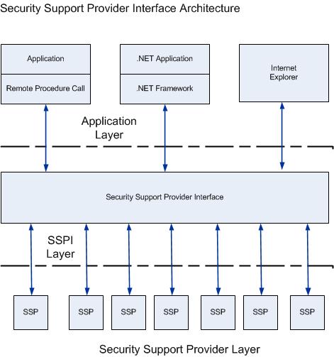
Security Support ProviderInterface Architecture
The SSPI in Windows provides a mechanism that carries authentication tokens over the existing communication channel between the client computer and the server. When two computers or devices need to be authenticated so that they can communicate securely, the requests for authentication are routed to the SSPI, which completes the authentication process, irrespective of the network protocol currently in use. The SSPI returns transparent binary large objects. These are passed between the applications, at which point they can be passed to the SSPI layer. The SSPI enables an application to use various security models available on a computer or network without changing the interface to the security system.
Security Support Provider
The following sections show the default SSPs that interact with the SSPI. The SSPs are used in different ways in Windows operating systems to enable secure communication in an unsecure network environment. The protocols used by these providers enable authentication of users, computers, and services; the authentication process, in turn, enables authorized users and services to access resources in a secure manner.
Using SSPI ensures that no matter which SSP you select, your application accesses the authentication features in a uniform manner. This capability provides your application greater independence from the implementation of the network than was available in the past.
Distributed applications communicate through the RPC interface. The RPC software in turn, accesses the authentication features of an SSP through the SSPI.
It’s been a while since I’ve blogged and in the interest of keeping a focus on training on new concepts, a friend suggested I follow John Zelle’s book- Python Programming – An introduction to Computer Science. The book is focused on Python but also provides some great detail on Computer Science principles along side programming.
As a result of having to do more programming at work, I thought I would chart my progress and register for a github account and document the end of chapter discussions, questions and exercises whilst learning some git concepts also
GitHub is a code hosting platform for version control and collaboration. It lets you and others work together on projects from anywhere. It has plenty of tutorials which can teach you GitHub essentials like repositories, branches, commits, and pull requests.
I have found it useful to my learning to document what I have learned, probably a repetitive learning concept and hopefully useful to others as it will be a public repository. If anyone feels like correcting anything or providing simpler and easier solutions, then feel free 🙂
SAML is an XML-based open-standard for transferring identity data between two parties: an identity provider and a service provider. SAML enables Single-Sign On (SSO), a term that means users can log in once, and those same credentials can be reused to log into other service providers. The OASIS Consortium approved SAML v2 in 2005. SAML 2.0 changed significantly from 1.1 and the versions are incompatible.
What is XML used for in relation to SAML?
SAML transactions use Extensible Markup Language (XML) to communicate between the identity provider and service providers. SAML is the link between the authentication of a user’s identity and the authorization to use a service.
How does authentication and authorization work in SAML?
SAML implements a secure method of transferring user authentications and authorizations between the identity provider and service providers. When a user logs into a SAML enabled application, the service provider requests authorization from the appropriate identity provider. The identity provider authenticates the user’s credentials and then returns the authorization for the user to the service provider, and the user is now able to use the application.
SAML authentication is the process of checking the user’s identity and credentials. SAML authorization tells the service provider what access to grant the authenticated user.
What is a SAML provider?
There are two primary types of SAML providers, serviceprovider, and identity provider.
The identity provider carries out the authentication and passes the user’s identity and authorization level to the service provider.
A service provider needs the authentication from the identity provider to grant authorization to the user.
Advantages of SAML
Users only need to sign in once to access several service providers. This means a faster authentication process and the user does not need to remember multiple login credentials for every application.
SAML provides a single point of authentication
SAML doesn’t require user information to be maintained and synchronized between directories.
Identity management best practices require user accounts to be both limited to only the resources the user needs to do their job and to be audited and managed centrally. Using an SSO solution will allow you to disable accounts and remove access to resources simultaneously when needed.
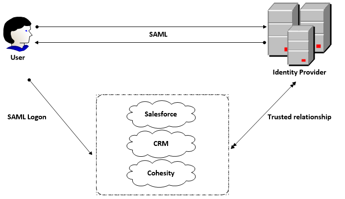
Visualising SAML
SAML Example
SAML uses a claims-based authentication workflow. When a user tries to access an application or site, the service provider asks the identity provider to authenticate the user. Then, the service provider uses the SAML assertion issued by the identity provider to grant the user access.
The user opens a browser and navigates to the service provider’s web application, which uses an identity provider for authentication.
The web application responds with a SAML request.
The browser passes the SAML request to the identity provider.
The identity provider parses the SAML request.
The identity provider authenticates the user by prompting for a username and password or some other authentication factor. NOTE: The identity provider will skip this step if the user is already authenticated.
The identity provider generates the SAML response and returns it to the user’s browser.
The browser sends the generated SAML response to the service provider’s web application which verifies it.
If the verification succeeds, the web application grants the user access.
The BIOS (Basic Input Output Operating System) is the first piece of software which runs and carries out the following tasks.
Performing POST – (Power-On Self-Test) in this phase the BIOS checks if the components installed on the motherboard are functioning
Basic I/O checks -This checks the peripherals such as the keyboard, the monitor and serial ports can operate to perform basic tasks.
Booting – The BIOS tries to boot from the devices connected (SSDs, HDDs, PXE, whatever) in order to provide an Operating System) to operate the computer.
It can also be a low level management tool providing some ability to tweak system features and settings
What is UEFI?
UEFI stands for Unifed Extensible Firmware Interface. UEFI was released in 2007 to provide a successor to BIOS to overcome limitations. Before this computers used the BIOS (Basic Input Output Operating System). Most UEFI firmware implementations provide support for legacy BIOS services.
UEFI Advantages over BIOS
32-bit/64/bit architecture rather than 16-bit
CPU independent architecture
Ability to use large disk partitions over 2TB. UEFI’s theoretical size limit for bootable drives is more than nine zettabytes, while BIOS can only boot from drives 2TB or smaller.
Flexible pre-OS environment, including network capability, GUI, multi language
Expanded BIOS with a GUI and mouse ability
UEFI Secure Boot feature, which employs digital signatures to verify the integrity of low-level code like boot loaders and operating system files before execution. If validation fails, Secure Boot halts execution of the compromised bits to stop any potential attack in its tracks. Secure Boot was added in version 2.2 of the UEFI specification
UEFI does not use the Master Boot Record (MBR) scheme to store the low-level bits that bootstrap the operating system. Under the MBR, these key bits reside in the first segment of the disk, and any corruption or damage to that area stops the operating system from loading. Instead, UEFI uses the GUID Partition Table (GPT) scheme and stores initialization code in an .efi file found in a hidden partition. GPT also stores redundant copies of this code and uses cyclic redundancy checks to detect changes or corruption of the data
C / C++ language used instead of assembly language
When building Windows 10 or Windows Server 2016 VM’s, it is recommended you build them with EFI firmware enabled. Moving from traditional BIOS/MBR to EFI (UEFI) firmware afterwards introduces some challenges later on down the line and can cause machines not to boot.
UEFI still cannot be used for auto deploying vSphere ESXi hosts but this may change in the future.
Cananonical and Windows have linked up to provide the ability to run Linux on Windows. Developers can also use Cygwin, MSYS, or run Linux in a virtual machine, but these workarounds have their own disadvantages and can overload systems. Bash on Windows provides a Windows subsystem and Ubuntu Linux runs on top of it.
Basically, Windows allows you to run the same Bash shell that you find on Linux. This way you can run Linux commands inside Windows without the needing to install a virtual machine, or dual booting Linux/Windows. You install Linux inside Windows like a regular application. This is a good option if you want to learn Linux/Unix commands.
How to enable
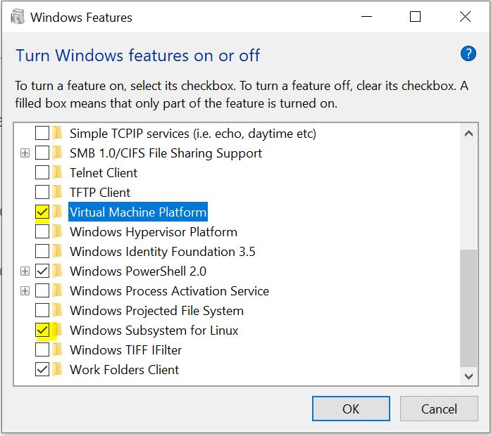
Go to Control Panel – Programs and Features – Turn Windows Features on and off.
Enable Windows Subsystem for Linux and Virtual Machine Platform
Reboot
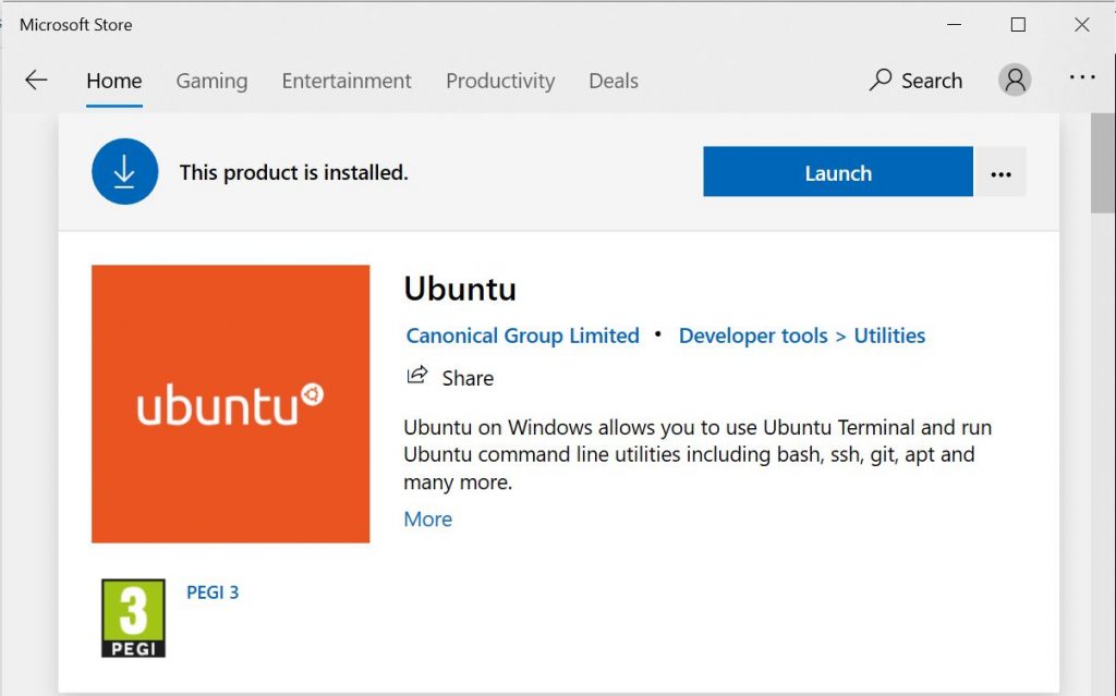
Go to the Windows store and search for Linux or Ubuntu. Install the distribution you want. In my case Ubuntu.
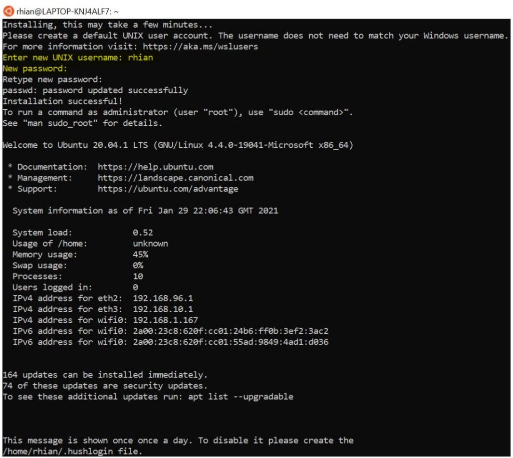
Once Ubuntu has installed, you will need to set up a username and password
This occurs for the first run. Bash shell will be available to use the next time you log in.
When you open the Bash shell in Windows, you are literally running Ubuntu. Developers can now run Bash scripts, Linux command-line tools like sed, awk, grep, and Linux-first tools like Ruby, Git, Python, etc. directly on Windows.
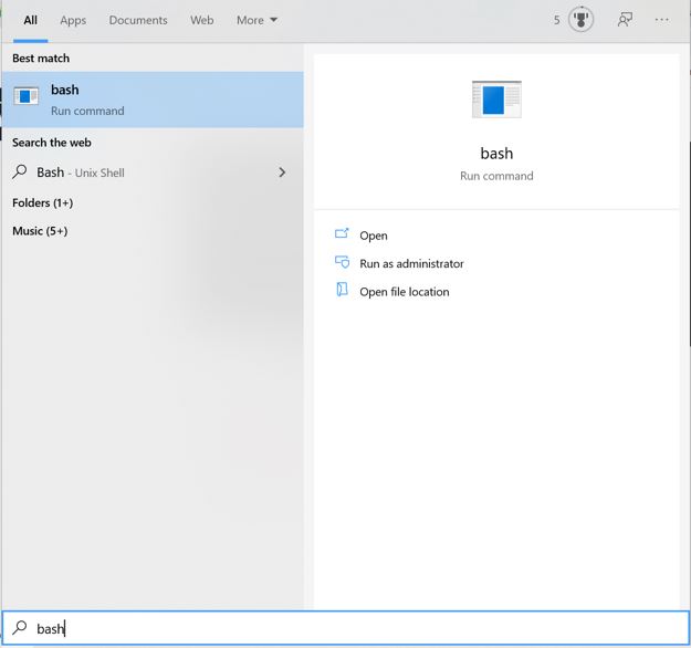
Search for bash or wsl in the Windows search box
Almost all Linux commands can be used in the Bash shell on Windows
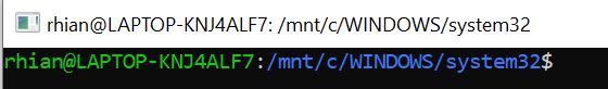
Opening bash and wsl will display as a “Run command” that can be selected to instantly open the bash shell. The difference with using either of these methods is that they open in the /mnt/c/Windows/System32 directory so you can browse the System32 subdirectory in Windows 10.
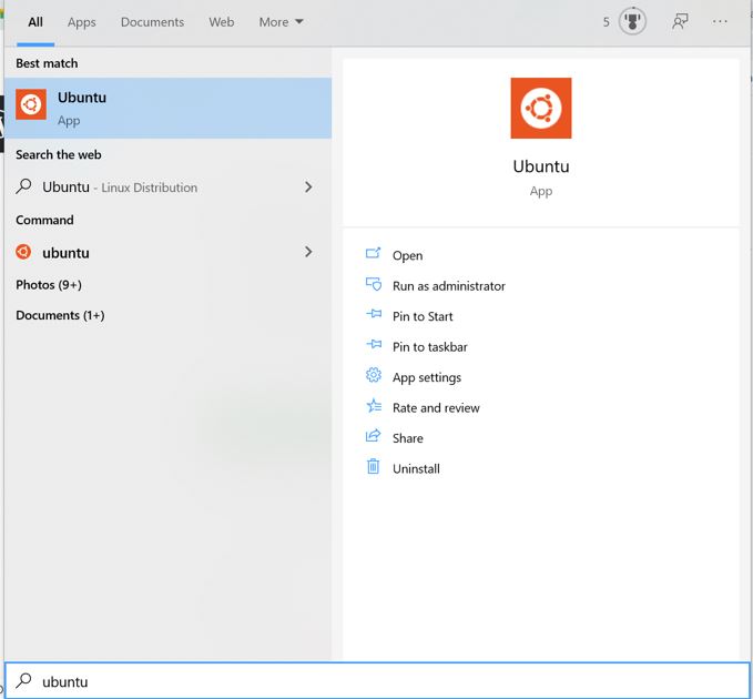
Or you can simply open the Ubuntu app
Examples
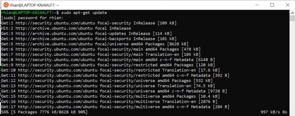
You can run sudo apt-get update and sudo apt-get upgrade to obtain and install updates along with all usual Linux commands.
This is an interesting feature of vSAN which came up in work recently. vSAN supports thin provisioning which lets you use as much capacity as currently needed where you can add more space in the future. One challenge to thin provisioning is that the VMDKs will not shrink when files within the guest O/S are deleted. An even bigger problem develops where many file systems will always direct new writes into free space rather than the old used space. Previous solutions to this involved manual intervention and storage vMotion to external storage or powering off an external machine. vSAN Trim/Unmap space reclamation solves this problem.
How does it work?
Modern guest O/S file systems have had the ability to reclaim no longer used space which are known as Trim/Unmap commands for the ATA and SCSI protocols. vSAN 6.7U1+ now has full awareness of Trim/Unmap commands sent from the guest O/S and can reclaim previously allocated storage as free space.
Benefits
Faster repair means that blocks which have been reclaimed do not need to be rebalanced or remirrored in the event of a device failure
Removal of dirty cache pages means that read cache can be freed up in the DRAM client cache as well as the hybrid vSAN SSD cache for use by other blocks. If removed from the write buffer then this reduces the number of blocks copied to the capacity tier.
Performance Impact
It does carry some performance impact as I/O must be processed to track pages which are no longer needed. The largest impact will be the UNMAPs issued against the capacity tier. vSAN 7U1 includes performance enhancements which help provide the fairness of UNMAPs in heavy write environments.
A minimum of virtual machine hardware version 11 for Windows
A minimum of virtual machine hardware version 13 for Linux.
disk.scsiUnmapAllowed flag is not set to false. The default is an implied true. This setting can be used as a “kill switch” at the virtual machine level should you wish to disable this behaviour on a per VM basis and do not want to use in guest configuration to disable this behaviour. VMX changes require a reboot to take effect.
The guest operating system must be able to identify the virtual disk as thin.
After enabling at a cluster level, virtual machines must be power cycled
Monitoring TRIM/UNMAP
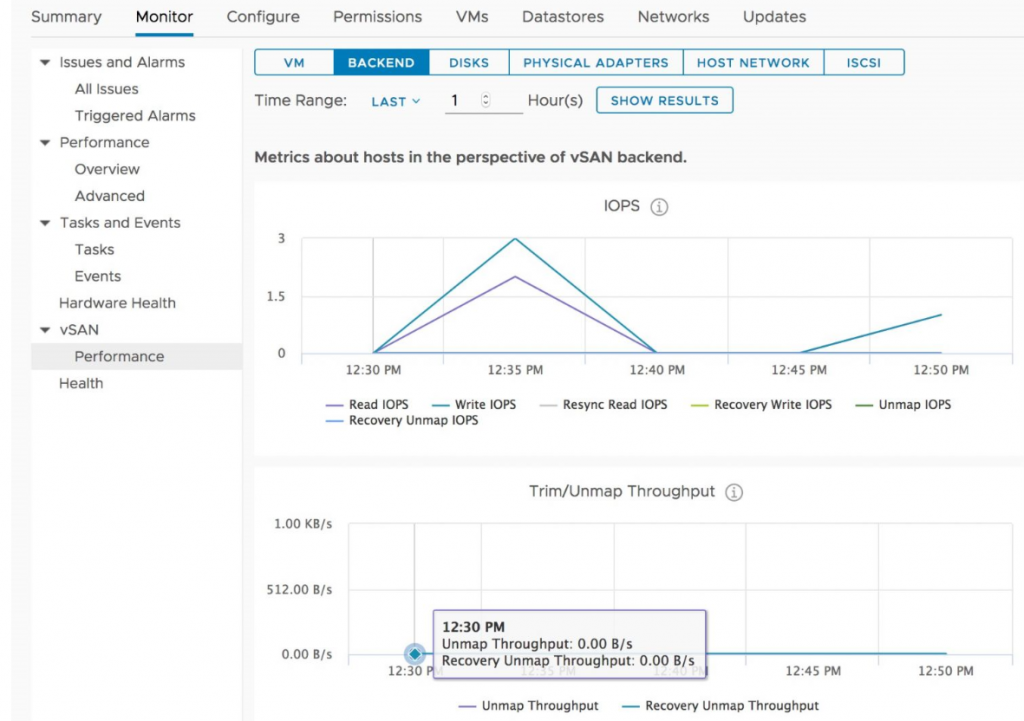
TRIM/UNMAP uses the following counters in the vSAN performance service for the hosts as seen in the figure below courtesy of VMware.
UNMAP Throughput – The measure of UNMAP commands being processed by the disk groups of a host.
Recovery UNMAP Throughput – The measure of throughput of UNMAP commands be synchronized as part of an object repair following a failure or absent object.
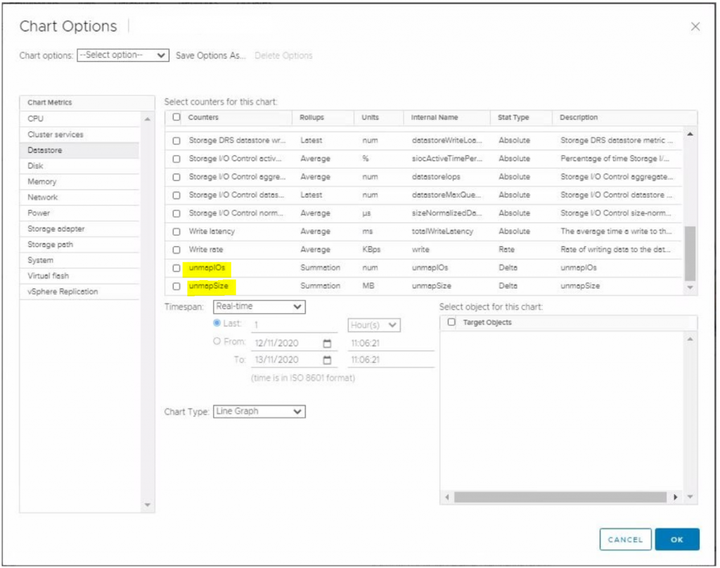
Using the advanced performance counters for a host will also show you the below counters
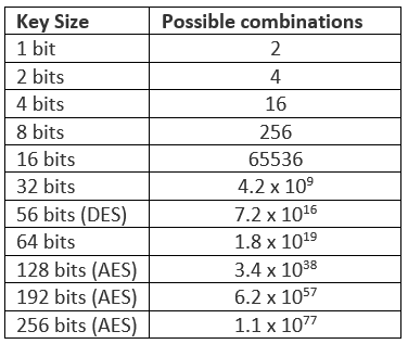
The Advanced Encryption Standard Instruction Set and the Intel Advanced Encryption Standard New Instructions allows specific Intel/AMD and other CPUs to do extremely fast hardware encryption and decryption. AES (Advanced Encryption Standard), is a symmetric block cipher which means that blocks of text which have a size of 128 bits are encrypted, which is the opposite to a stream cipher where each character is encrypted one at a time. The algorithm takes a block of plain text and applies alternating rounds of substitution and permutation boxes to it which are separate stages. In AES, the size of each box is 128, 192 or 256 bits, depending on the strength of the encryption with 10 rounds applied for a 128-bit key, 12 rounds for the 192-bit key, and 14 rounds for the 256-bit key, providing higher security.
The figure below shows that potential key combinations exponentially increase with the key size. AES-256 is impossible to break by a brute force attack based on current computing power, making it the strongest encryption standard. However longer key and more rounds requires higher performance requirements. AES 256 uses 40% more system resources than AES 192, and is therefore best suited to high sensitivity environments where security is more important than speed.
AES Block Cipher Modes
There are different AES block cipher modes that are part of AES.
Electronic Code Book
The simplest block cipher mode is Electronic Code Book. This cipher mode just repeats the AES encryption process for each 128-bit block of data. Each block is independently encrypted using AES with the same encryption key. For decryption, the process is reversed. With ECB, identical blocks of unencrypted data, referred to as plain text, are encrypted the same way and will produce identical blocks of encrypted data. This cipher mode is not ideal since it does not hide data patterns well.
Cipher Block Chaining
A newer block cipher mode was created called Cipher Block Chaining. CBC’s aim is to achieve an encryption method that encrypts each block using the same encryption key producing different cipher text, even when the plain text for two or more blocks is identical. Cipher Block Chaining addresses security weaknesses with ECB.
AES-XTS Block Cipher mode
AES-XTS Block Cipher Mode is a new block cipher mode and designed to be stronger than other modes. It eliminates potential vulnerabilities from sophisticated side channel attacks used to exploit weaknesses within other modes. XTS uses two AES keys. One key performs the AES block encryption; the other is used to encrypt what is known as a Tweak Value. This encrypted tweak is further modified with a Galois polynomial function (GF) and XOR with both the plain text and the cipher text of each block. The GF function ensures that blocks of identical data will not produce identical cipher text. This achieves the goal of each block producing unique cipher text given identical plain text without the use of initialization vectors and chaining. Decryption of the data is carried out by reversing this process.
What is AES-NI?
Intel AES New Instructions (Intel AES-NI) is a new encryption instruction set which contains improvements to the AES algorithm and accelerates the encryption of data in the Intel Xeon processor family and the Intel Core processor suite. AES is a symmetric block cipher that encrypts/decrypts data through several rounds. It is part of the FIPS standard.
There are seven new instructions. The instructions have been implemented to perform some of the complex and performance intensive steps of the AES algorithm. Hardware is used to accelerate the AES algorithms. Intel say that AES-NI can be used to accelerate the performance of an implementation of AES by 3 to 10x over a total software implementation.
How does it work?
A fixed block size of plain text is encrypted several times to produce a final encrypted output. The number of rounds (10, 12, or 14) used depends on the key length (128, 192, or 256). Each round feeds into the following round. Each round is encrypted using a subkey that is generated using a key schedule
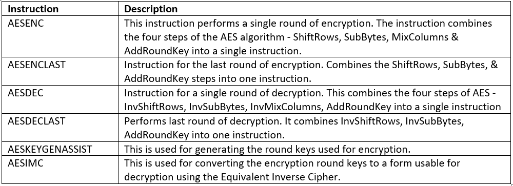
What are the six new instructions?
The new instructions perform several computationally intensive parts of the AES algorithm using fewer clock cycles than a software solution.
Four of the new instructions accelerate the encryption/decryption of a round
Two new instructions are for round key generation.
Improved security
The new instructions also improve security by preventing side channel attacks on AES. Encryption and decryption are performed completely in hardware without the need for software lookup tables. By running in data-independent time and not using tables, they help in eliminating the major timing and cache-based attacks that target table-based software implementations of AES. In addition, AES is simple to implement, with reduced code size, which helps reducing the risk of introducing security flaws, such as difficult-to-detect side channel leaks.
Most of the cloud providers such as Amazon, Google, IBM, Microsoft offer instances equipped with this Intel extension and use it as security feature in their products. AES can be used in applications where confidentiality and integrity is of highest priority. If cryptographic strength is a major factor in the application, AES is the best suited algorithm.
VMware Cloud Foundation provides a software-defined stack including VMware vSphere with Kubernetes, VMware vSAN, VMware NSX-T Data Center, and VMware vRealize Suite, VMware Cloud Foundation provides a complete set of software-defined services for compute, storage, network security, Kubernetes management, and cloud management.
What is vCloud Foundation Lab Constructor?
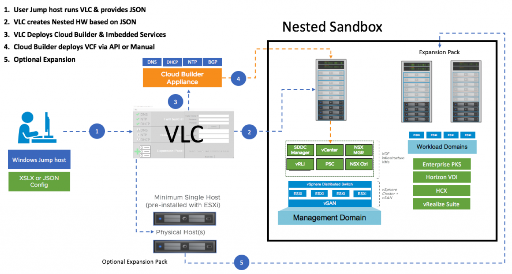
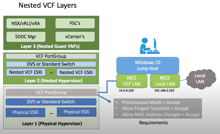
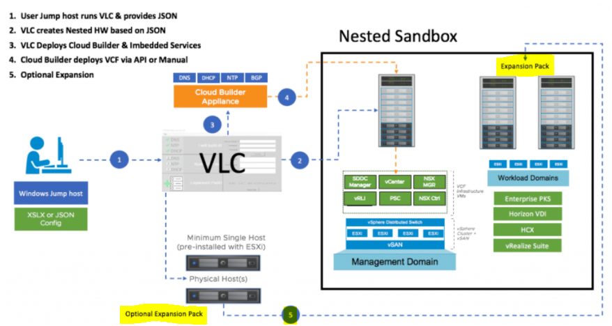
VLC is an automated tool built by Ben Sier and Heath Johnson that deploys an entire nested Cloud Foundation environment onto a single physical host or vSphere Cluster. It is an unsupported tool, this will allow you to learn about VCF with a greatly reduced set of resource requirements. VLC deploys the Core SDDC components in the smallest possible form factor. Specifically, components like the vCenter and vRealize Log Insight nodes are deployed in the tiny, and xsmall format as specified in a JSON config file. With these two stages, the reduction of physical resources needed to deploy the VLC nested lab components becomes possible on a single physical host with 12 CPU Cores, 128 GB RAM, and 2 TB of SSD Disk.
An overall view of what VLC looks like
DownloadVLC
You will need to register at http://tiny.cc/getVLC and then you will be provided with a zip file.
vExpert Program – If you are a vExpert you can log in and download the software for free however there is not an NSX-T license available here, only in VMUG I believe.
VCF customers – Can download what you need from the My VMware Portal
Pre-requisites
Step 1
You need a single physical host running ESXi 6.7+ with 12 cores, 128 GB RAM and 800 GB SSD. This is the minimum requirement for using VLC and you will need to configure the host in 1 of 4 configurations below.
Standalone ESXi (No vCenter) using a vSS
ESXi host with vCenter using vSS
Single ESXi host in a cluster using vDS
Multiple ESXi hosts in a cluster using vDS
If you are running multiple hosts in a vSAN cluster then run the following command on all hosts because you will be in effect nesting a vSAN within a vSAN
esxcli system settings advanced set -o /VSAN/FakeSCSIReservations -i 1
If you are deploying to a single physical host don’t worry about physical VLANs as all the traffic will reside on that single physical host. If you are deploying to a vSphere cluster you’ll need at least 1 VLAN (10 is the default) physically configured and plumbed up on your physical switch to all hosts in that cluster. If you intend to do anything with NSX (AVN’s are the common thread) you’ll also need 3 additional VLANs (11-13 are default)
If in a cluster configuration, disable all HA and DRS and vMotion on the physical host(s).
You will need a virtual switch (VSS or vDS) with the MTU set to 9000
On the vSwitch, create a portgroup for VCF with VLAN Trunking (0-4094) enabled. On the portgroup (not the switch) set the following security settings:
I chose to deploy my lab on one host with a vDS switch.
Step 2
Build a Windows-based jump host on this ESXi host as a VM and install the following software.
Windows 10/2012/2016 (Older versions are not supported)
Powershell 5.1+
PowerCLI 11.3+
OVFTool 4.3+ (64bit)
Net Framework
VMXNET3 NICs – 1500 MTU
On this jump host, attach two virtual NICs.
Attached one NIC to your local LAN Network so you can RDP to it.
Attach the second NIC to the VCF PortGroup created in Step 1 and configure it with the IP 10.0.0.220. Set the DNS on the second NIC to 10.0.0.221. The 10.0.0.221 address will be the address assigned to the Cloud Builder appliance, by default. VLC will modify the Cloud Builder appliance so that it provides specific services, like DNS, for the nested environment. Thus, this using this IP for DNS will allow you to access the nested VCF environment when using the default configuration file in Automated mode.
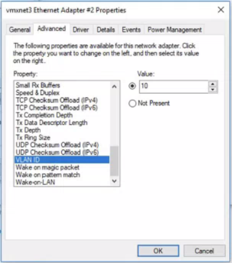
This second NIC will also need to be configured in the NIC properties to use the VLAN of your management network. In the default Automated VLC configuration this is VLAN 10.
The jump host should look like the below
On the jump host, do the following
Disable Windows Firewall.
Turn off Windows Defender Real-time Scanning. Note: this has a habit of resetting after reboots of the Windows VM.
Step 3
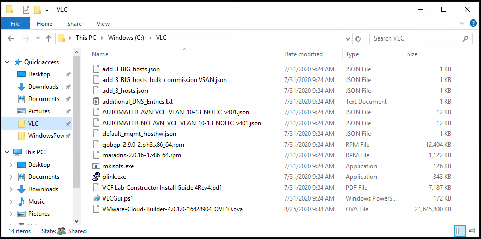
On the Windows jump host, create a local disk folder for VLC. This must be a local attached disk (i.e. “C:\VLC\ ”) as mapped Network drives will fail.
Download the VCF Software (Cloud Builder OVA) into this folder.
You used to have to download the vSphere ESXi ISO that matches the version required for VCF. The easiest method to do this was to simply copy the .iso file located on the Cloud Builder appliance but to make this even easier, VLC now provides an option in the setup GUI where it will download this file directly from the Cloud Builder appliance that it deploys.
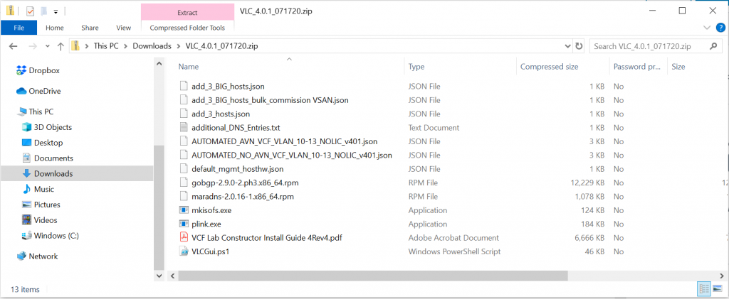
Download and extract the VLC package to this folder as well
Install anything extra you need like Putty, WinSCP and Notepad++
Step 4
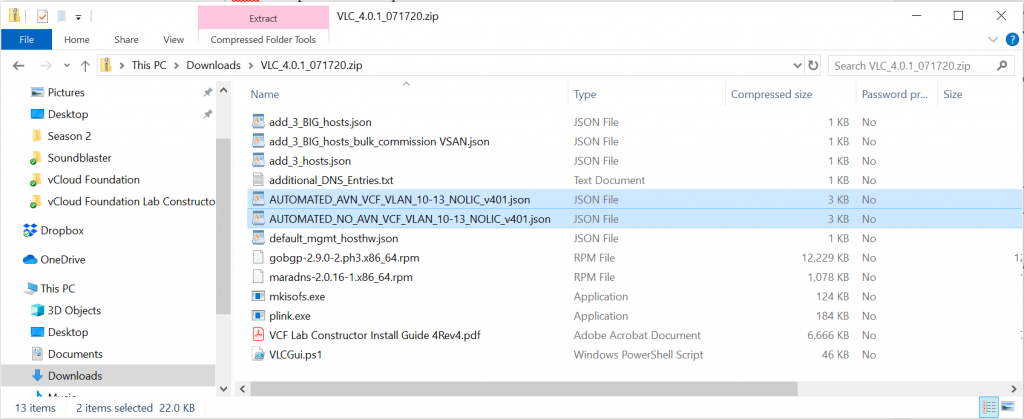
We now need to edit one of two files. You have a choice of Automated_AVN or Automated_No_AVN when deploying VLC.
Multiple sample bringup JSON formatted files are provided with VLC. The selection of the bringup JSON file will dictate if AVN will be implemented at bringup or not. Regardless of which bringup file is to be used, you will need to edit the file to be used in order to define the license keys to be used. The default configuration files do not include any license keys. Using a text editor, edit the appropriate file, as desired with an ESXi license, vCenter license, NSX-T license and vSAN license.
Step 5
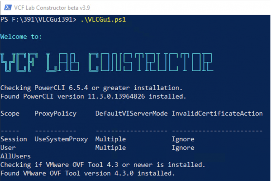
Either open a Powershell window (as Administrator) and execute the VLC PowerShell Script “C:\VLC\VLCGUi.ps1” or right click on the VLCGUI.ps1 and select ‘Run with PowerShell’.
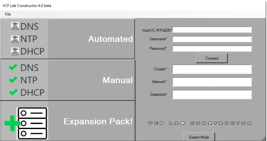
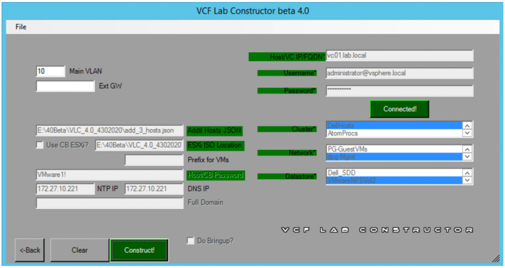
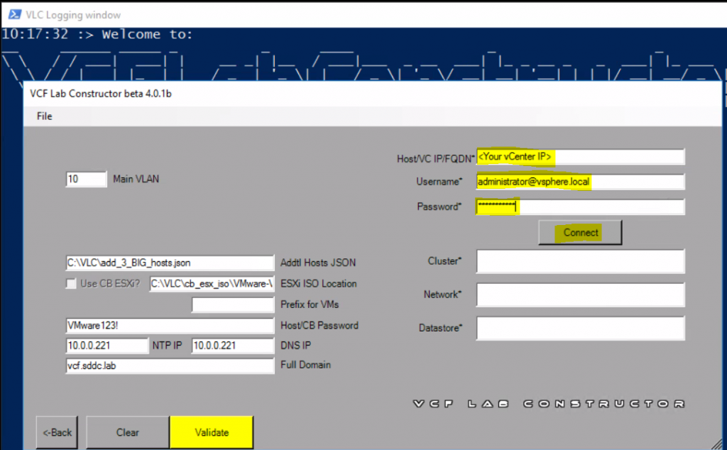
VLC UI will Launch
Once the above screen completes, you will see the below screen. Select the “Automated” Button. This will build your first four hosts for the Management Domain. This is done by creating four virtual nested ESXi hosts. These nested hosts are automatically sized and created for you. You are able to configure the hostnames and IP addresses to be used within the configuration file that you provide the VCF Lab Constructor
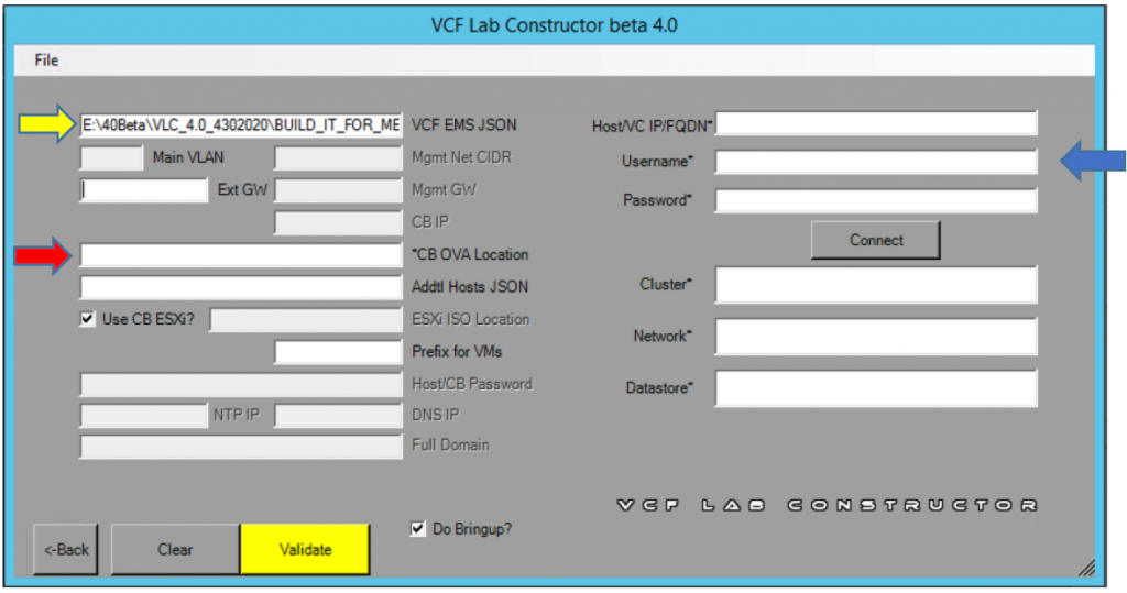
Click on the field titled ’VCF EMS JSON’ and select the JSON file that you just entered the license keys for.
Click on the CB OVA Location field to select the location of the CB OVA.
(Optional) Enter the External GW for the Cloud Builder Appliance to use. This allows you to point to a gateway that will allow internet access.
Click the Connect Button
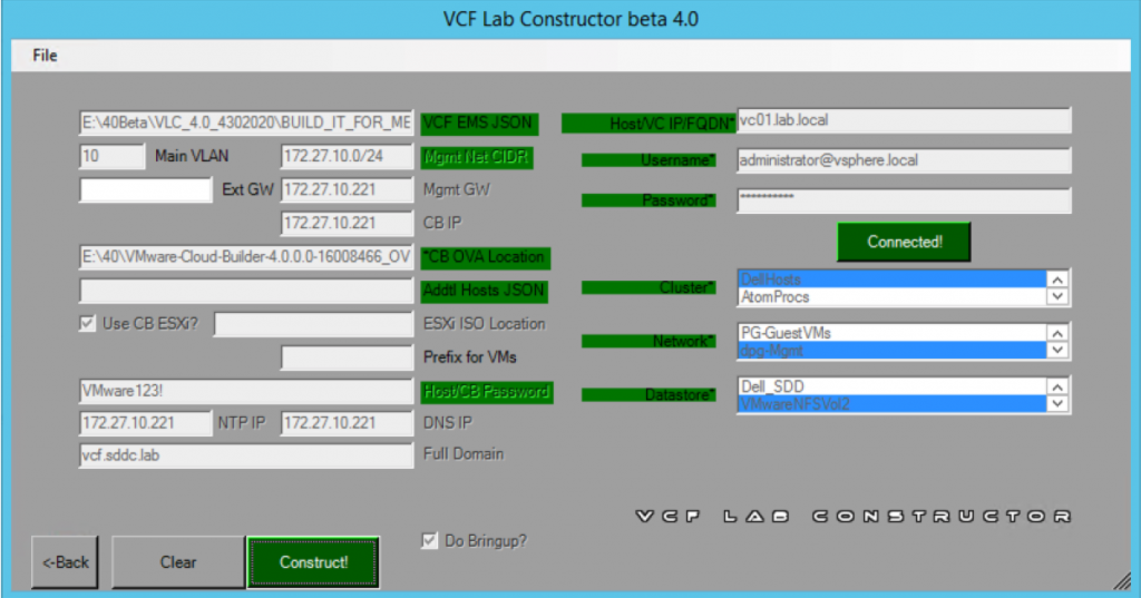
VLC will connect to the host or vCenter you specified and will validate all necessary settings. It will then populate the Cluster, Network, and Datastore fields with information gathered from your environment.
Select the cluster, network (port group) and datastore that you desire VLC to install the nested lab to. The Cluster field will not display any value if you are deploying directly to a single ESXi host.
** If your port group does not show up, you need to check to see if the previous security settings have been set explicitly on the port group and not just the switch.
Click the yellow Validate button
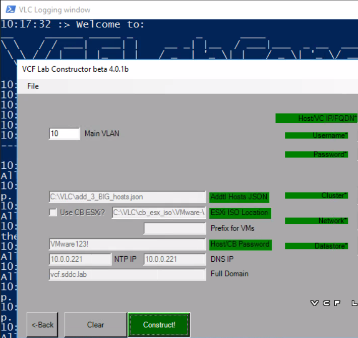
As VLC validates the information, it will mark the fields in green. When everything has been validated, the Validate button will change to a green button that says ‘Construct’.
Note the Bring up box. his is a fully documented process in the installation of VCF. Using the VCF Lab Constructor will allow you to manually do this so you can follow the steps of the official VMware Documentation, or if you check the box in the GUI the VCF Lab Constructor will complete Bring-up for you automatically.
Click Construct to begin the deployment of VMware Cloud Foundation.
The process will take some time to complete. On average, expect to wait three and a half hours for the deployment process to complete.
Logging
During bringup logs can be found in the Cloudbuilder appliance in the /var/log/vmware/vcf/bringup directory – Check vcf-bringup-debug.log in that directory.
For problems deploying VC and PSC on bringup look in /var/log/vmware/vcf/bringup/ci-installer-xxxx/workflow_xxxx/vcsa-cli-installer.log
After bringup you can look at the SDDC Manager for logs. The are all rooted in the /var/log/vmware/vcf folder. Depending on what operation you are performing you can look into one of the other folders.
Domain Manager – Used when creating/deleting/expanding/shrinking new workload domains:/var/log/vmware/vcf/domainmanager/domainmanager.log
Operations Manager – Used when commissioning/decommissioning hosts and resource utilization collection:/var/log/vmware/vcf/operations/operationsmanager.log
LCM – Used for Life cycle management activities like downloading bundles, applying updates: /var/log/vmware/vcf/lcm/lcm.log
Accessing the VCF UI
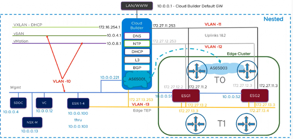
To gain network access when the VCF components are installed on layer 3, your jump host will need a NIC with multiple IP addresses or you will need multiple NICs. Be aware that because everything is nested inside Layer 2 all network traffic is being broadcast back up to Layer 1 port groups. Simply having your jump host on this subnet or port group and listening on the default VCF subnet i.e. (192.168.0.0) will allow you to access everything in layer 3. The jump host can also be nested at layer 1 or a physical desktop that has access to the same subnet. Nesting it at Layer 1 has the best performance.
The below diagram courtesy of VMware shows the networks which are created
Further tasks– Expanding the number of hosts
Using the Expansion pack option will now allow you to scale out hosts
When clicking on the Expansion pack option, you get the below screen
When you have used the Automated method to deploy your environment. VLC has configured the Cloud Builder appliance to provide essential infrastructure services for the managment domain. Before adding additional hosts, you will need to add the appropriate DNS entries to the Cloud Builder configuration. You can use the information below or further down the post, I go through using the expansion pack option when running the VLCGui.ps1 script again and modifying some VLC files.
Adding DNS entries for extra hosts
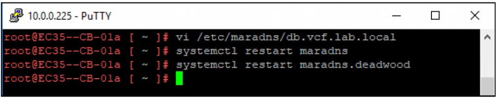
Use SSH to connect to your Cloud Builder VM and log in using the username (admin) and the password that you specified in the VLC GUI when you deployed the environment.
You will need to edit the DNS “db” file for the zone specified. As an example, assume that the domain ‘vcf.sddc.lab’ was used during the creation of the nested environment. This would mean the zone file would be located here: /etc/maradns/db.vcf.sddc.lab
After making your changes and saving the file you will need to reload maradns and the maradns.deadwood services. MaraDNS takes care of forward lookups and Deadwood takes care of Reverse DNS.
You would follow this same procedure for adding DNS entries for vRSLCM, vROps, vRA, Horzion, or any other component. Note: Certain software (like vROps, vRA, and Horizon) are not automated in VCF 4.0 via SDDC Manager. You may need to follow the manual guidance presented in the VCF documentation to deploy these software packages.
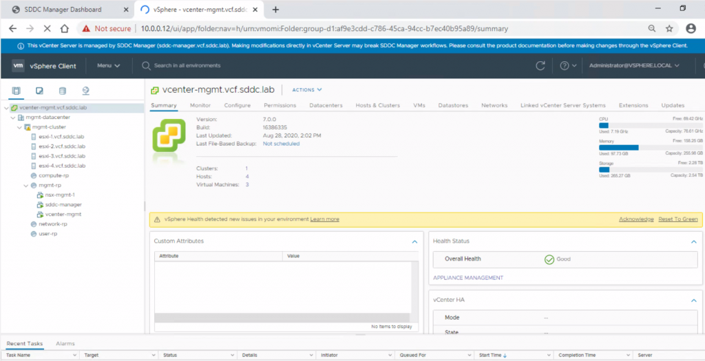
Logging into the SDDC
From the jump host you can log into the following
Hosts = 10.0.0.100-103
vCenter IP = 10.0.0.12 (https://vcenter-mgmt.sddc.lab)
Have a click around and get familiar with the user interface
What if we want to create a workload domain?
The initial part of this script deploys the 4 node ESXi management domain so what if we want to create some more hosts for a workload domain for the products below?
K8s
Horizon
HCX
vRealize suite
Step 1
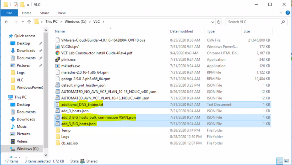
First of all we are going to use the below 3 files and add DNS entries
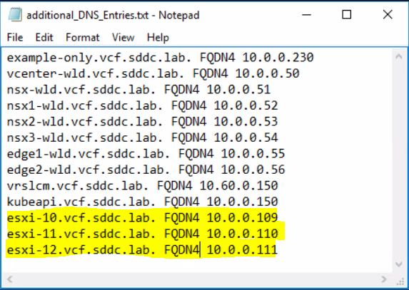
Open the additional_DNS_Entries.txt file and add in the new 3 hosts. In my case it looks like this.
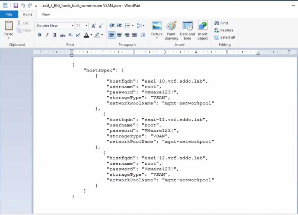
The next file to look at is the add_3_BIG_hosts_bulk_commission VSAN.json
Next we will have a look at the add_3_BIG_hosts_bulk_commission VSAN.jso file. This is used by the vCloud Foundation software itself.
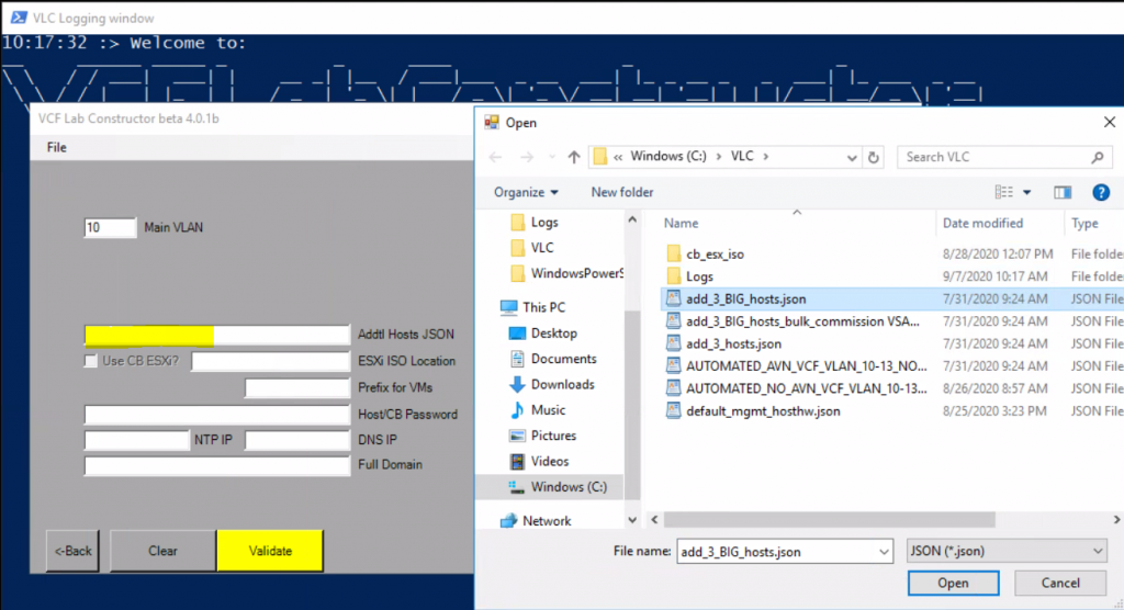
So now we need to run the VLCGui.ps1 script again located in c:\VLC to get to the point where we see the expansion pack option below.
Run Powershell and run .\VLCGui.ps1
Click on Expansion pack
Add in 10 for the main VLAN
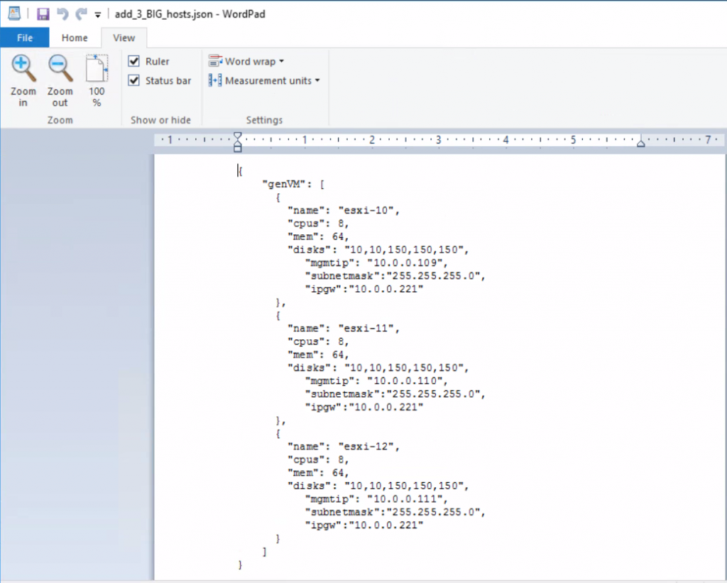
In the Addtl Hosts JSON file box, select your add_3_BIG_hosts.json
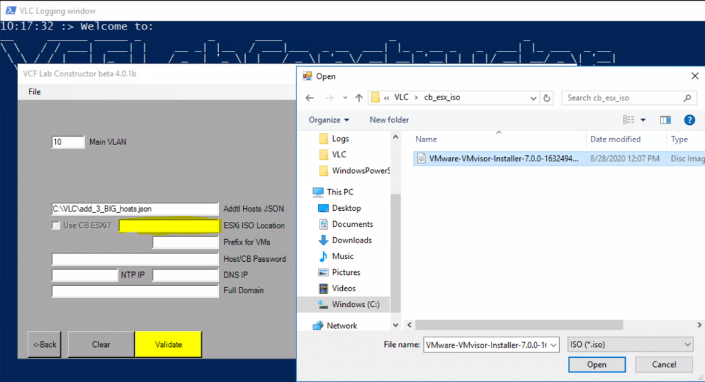
In the ESXi ISO Location, navigate to c:\VLC\cb_ESX_iso and select the ESXi image
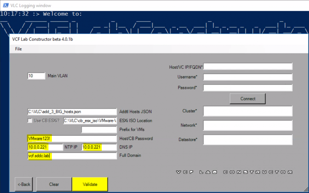
Next add in the host password which is VMware123
Add in the NTP IP which points to the CloudBuilder appliance on 10.0.0.221
Add in the DNS IP which points to the CloudBuilder appliance on 10.0.0.221
Add in the domain name for the lab which is vcf.sddc.lab
Next put in your vCenter IP, username and password and click Connect
When connected, choose your cluster, network and datastore like you did when configuring this for the inital management host deployment and then click Validate and everything should be green
Click Construct
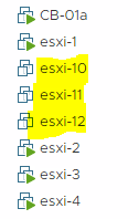
You will now see in your vCenter the extra hosts being created
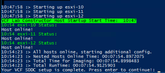
Once finished, you should see the below message in PowerShell. You can see it took a total of around 8 minutes.
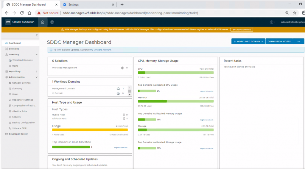
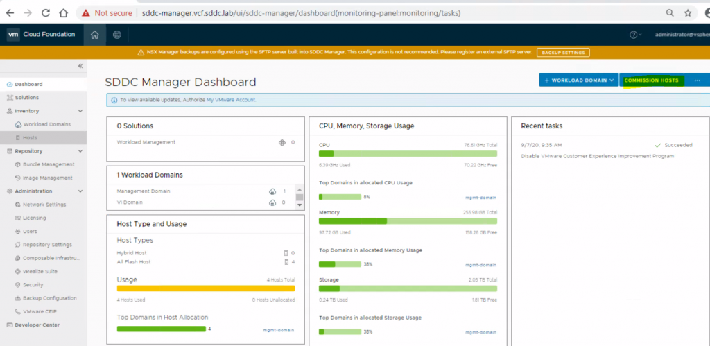
The hosts are now ready to be commissioned into SDDC Manager so we go back to sddc-manager.vcf.sddc.lab and click on Commission hosts in the top right hand corner.
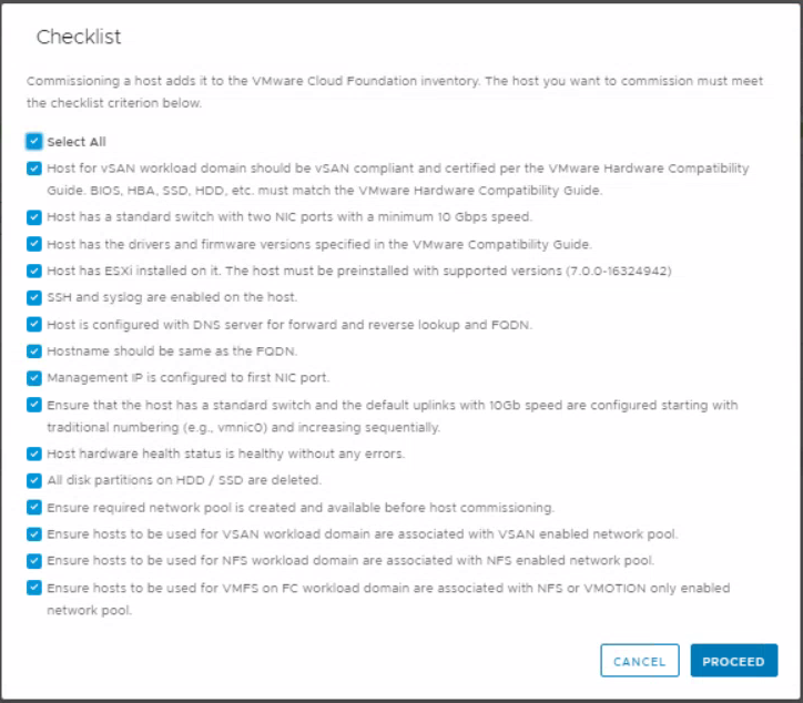
Say Yes to the entire checklist and click Proceed
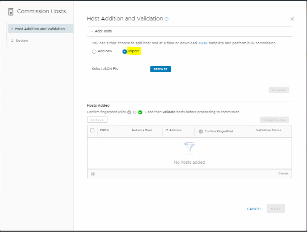
Next we will use the Import button to add the additional hosts.
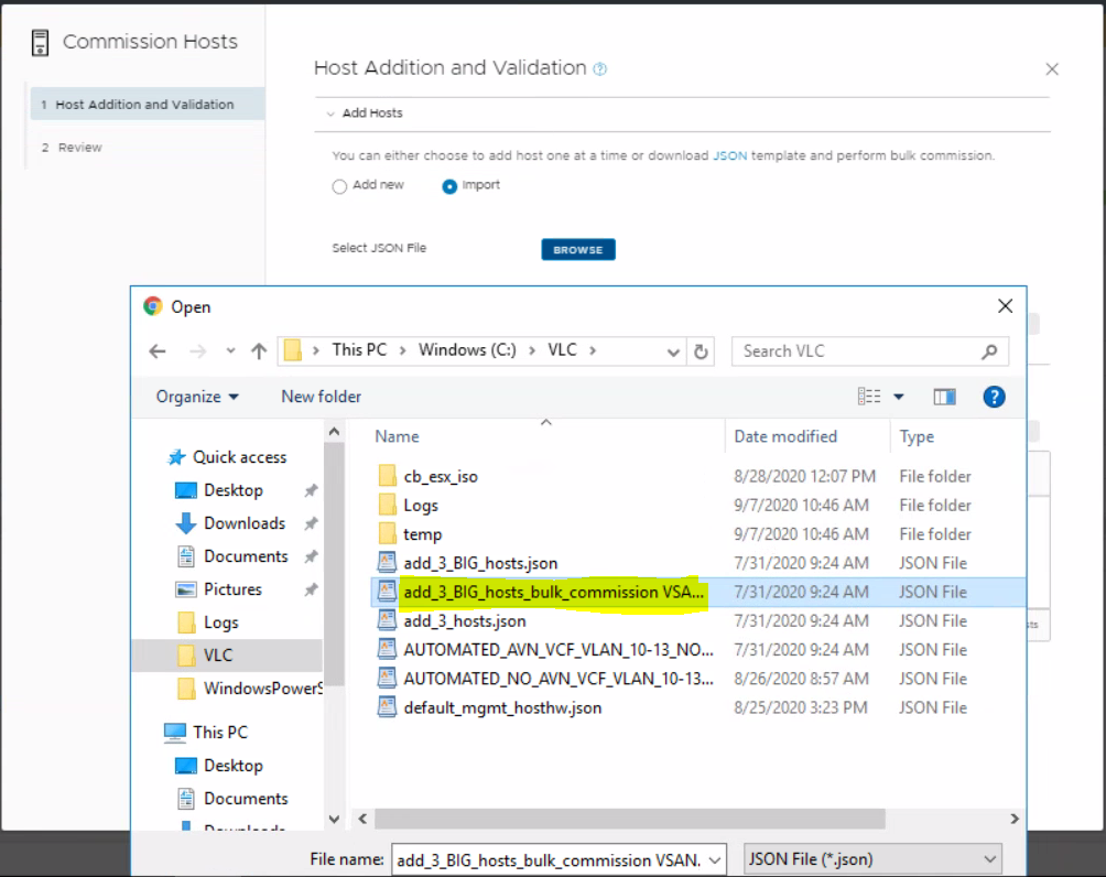
Choose the add_3_BIG_hosts_bulk_commission VSAN.json file
Click upload
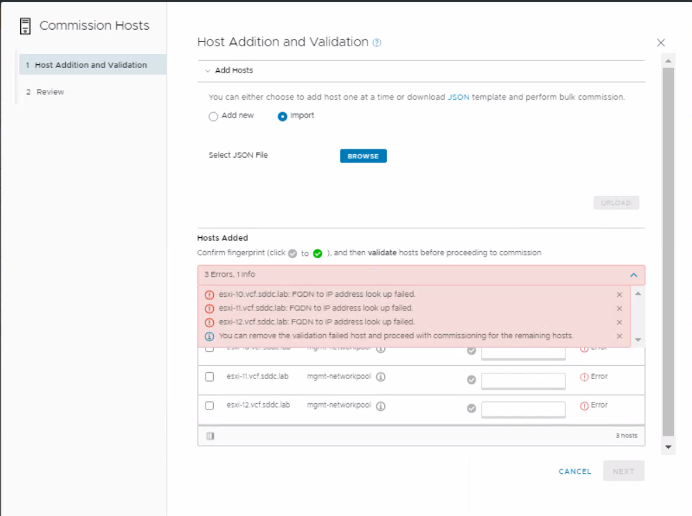
If you have a problem where you get the below message then follow the steps below
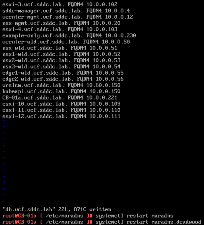
Log into the Cloudbuilder appliance using root and VMware123! and run the below command
Press i to insert new data and add in your new hosts in the same format as the other entries
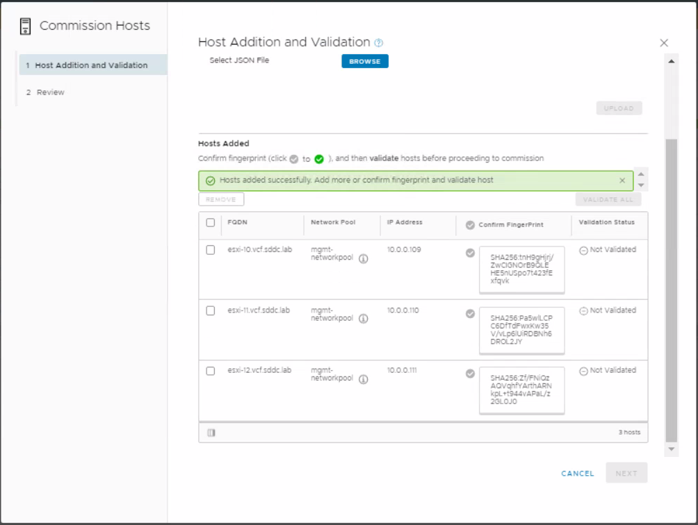
Go back to SDDC manager and try an upload again and everything should be fine.
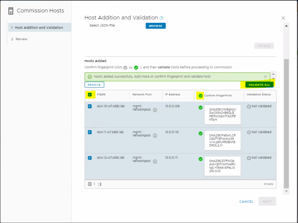
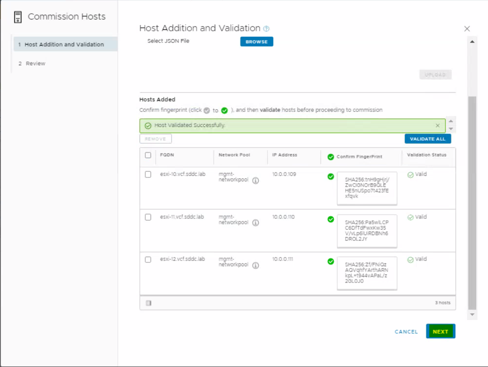
Select all hosts, click on the tickbox on the column saying Confirm FingerPrint and click Validate
Click Next
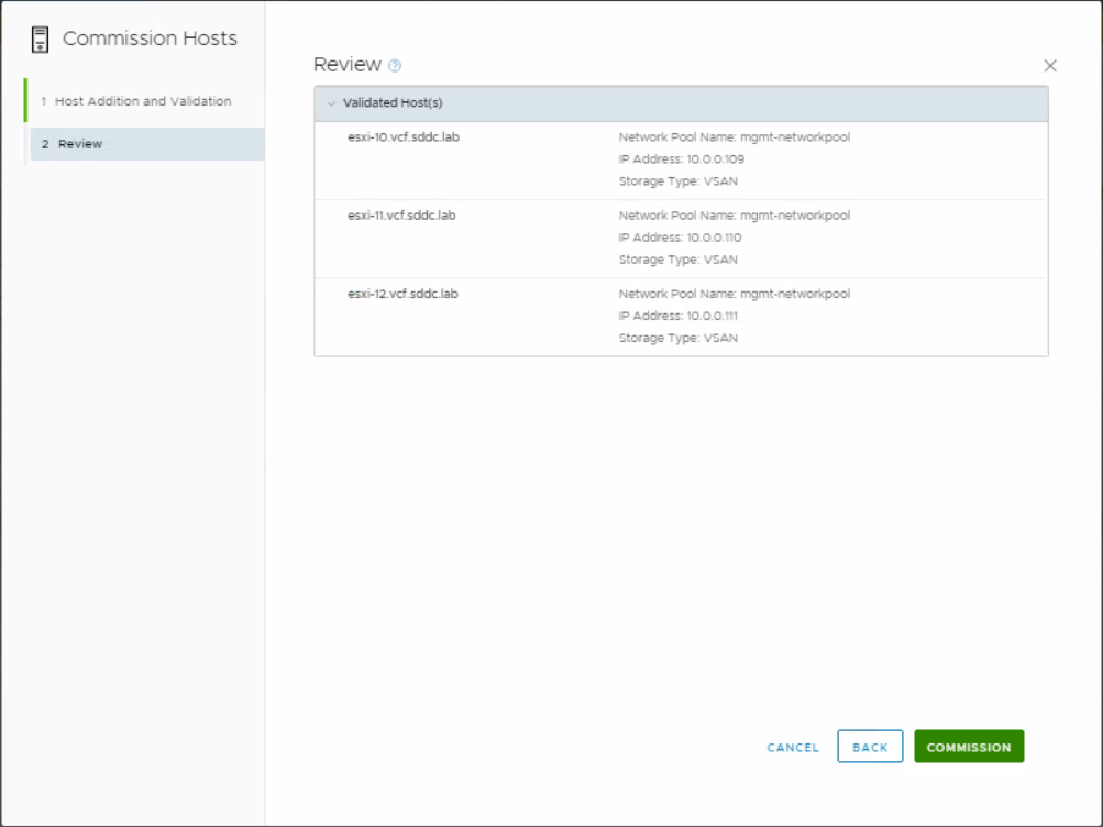
Review
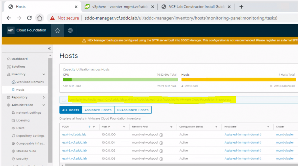
You will see a message in SDDC Manager saying the hosts are being commissioned
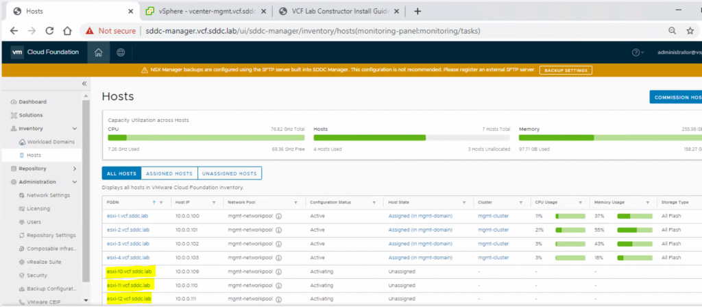
Once commissioned, you will see them as unassigned hosts
Following on from this, I will be following the VLC manual to enable vSphere with Kubernetes on VLC
Enabling Kubernetes on VLC
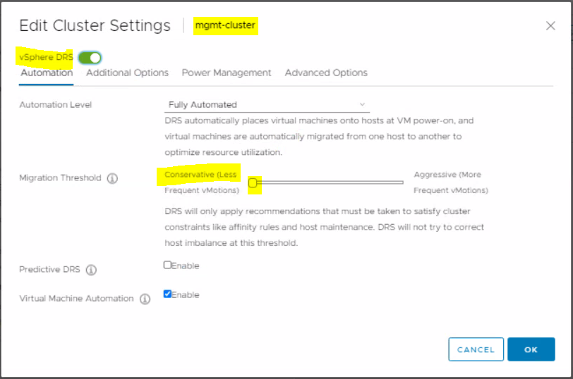
In vcenter-mgmt.vcf.sddc.lab, set DRS to Conservative on mgmt-cluster
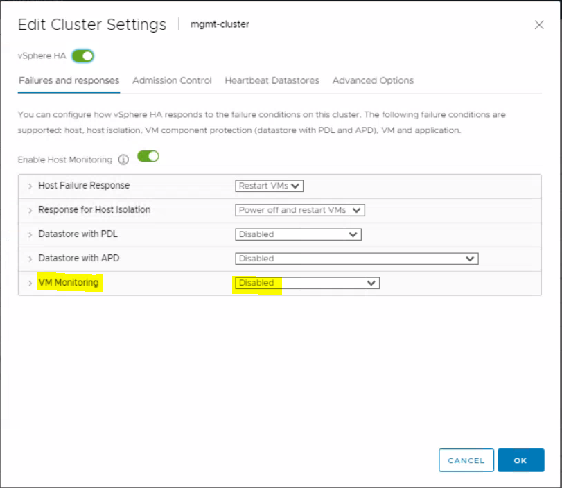
In vcenter-mgmt.vcf.sddc.lab, set VM Monitoring to Disabled
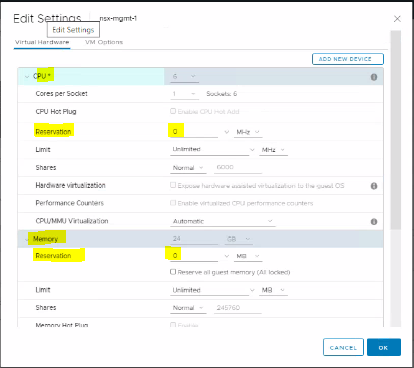
In vcenter-mgmt.vcf.sddc.lab, remove the CPU and memory reservation on nsx-mgmt-1
Make sure you have enough licensing available and add additional licenses if required.
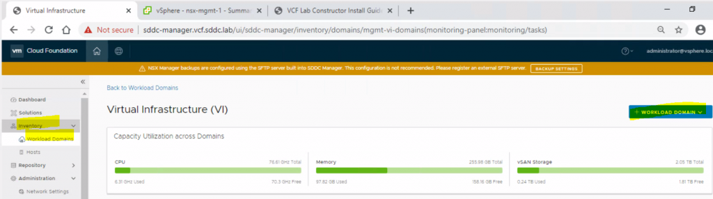
We can now create a VI workload domain with the 3 extra hosts we added before. In sddc-manager.vcf.sddc.lab, click on the menu and select Inventory > Workload domains and click the blue + Workload Domain button. Then select the dropdown VI – Virtual Infrastructure
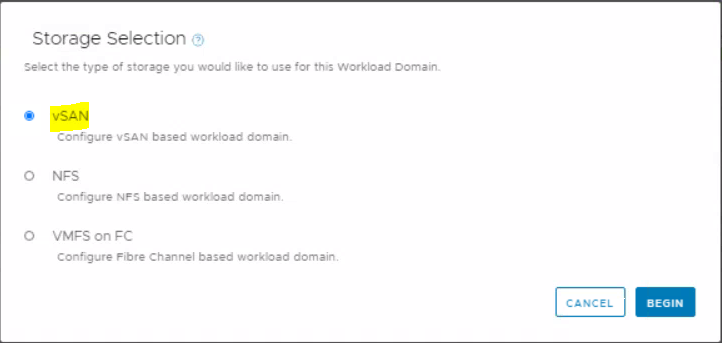
Select vSAN on Storage Selection and click begin
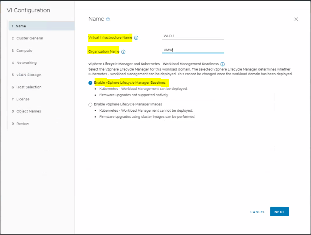
Enter a Virtual Infrastructure Name and Organisation name
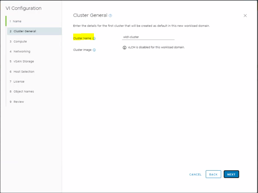
Enter a cluster name and click Next
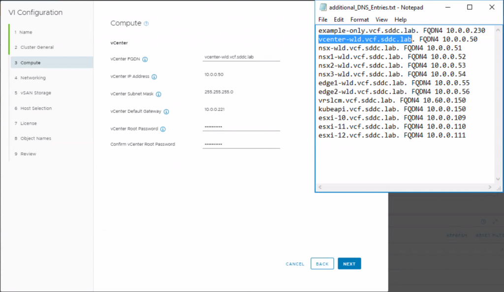
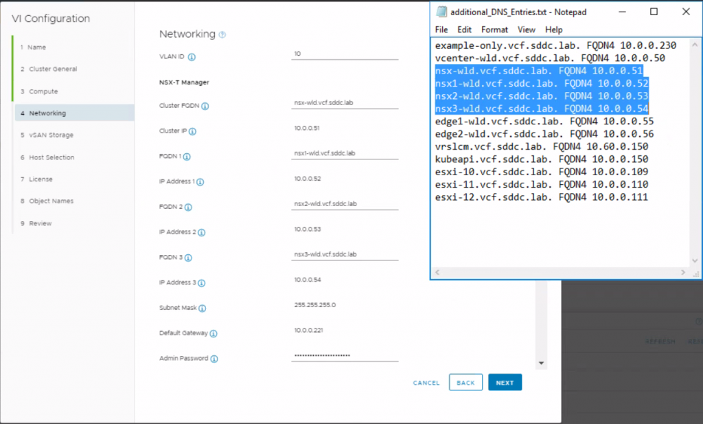
Fill in the details of the workload domain vCenter. I have screenshotted the file additional_DNS_Entries.txt from the c:\VLC folder next to this for reference. I used the password used throughout this lab which is VMware123! to keep everything easy.
Next we need to fill in the NSX information. Again the information has come from the additional_DNS_Entries.txt from the c:\VLC folder and the password needs to be stronger so I have used VMware123!VMware123!
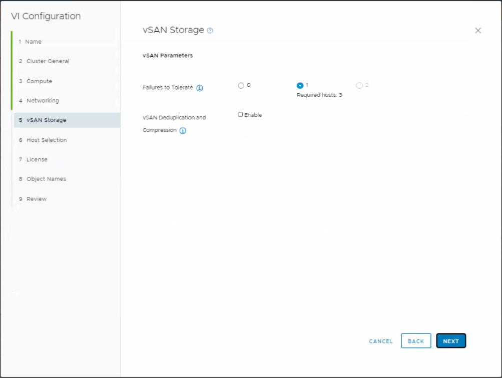
Leave the vSAN storage parameters as they are
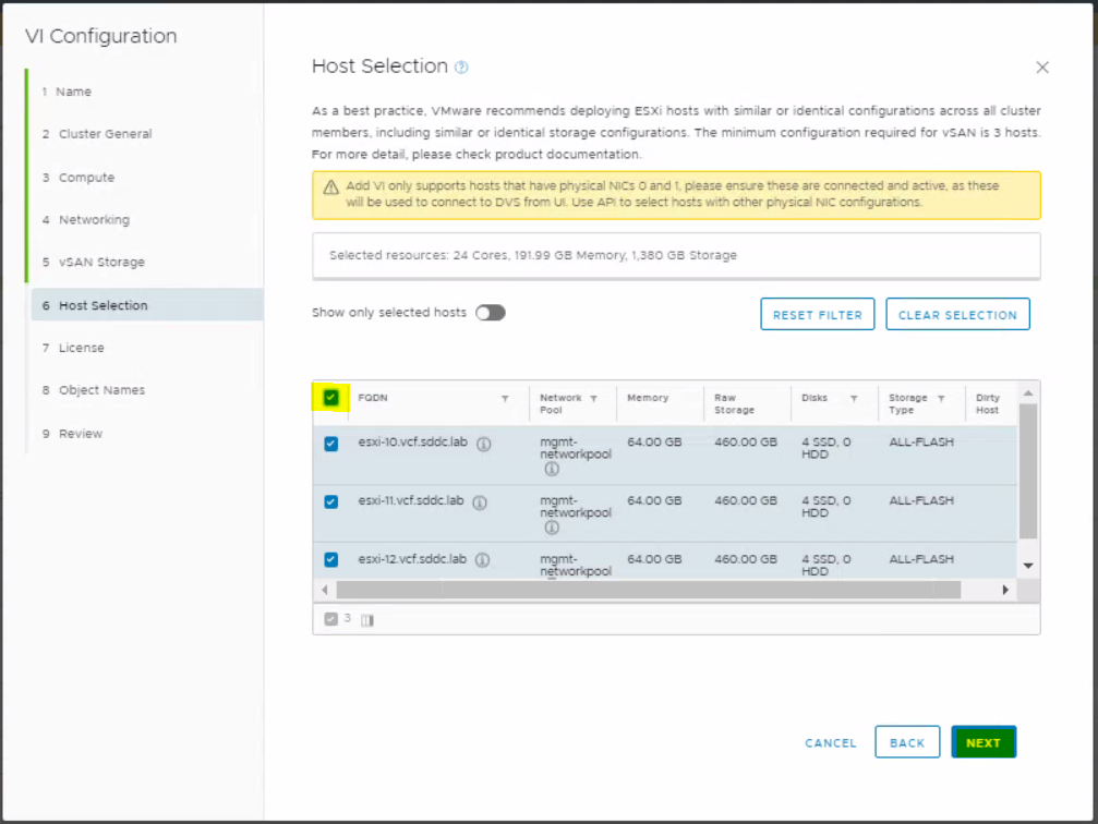
On the Host selection page, select your 3 new unassigned hosts
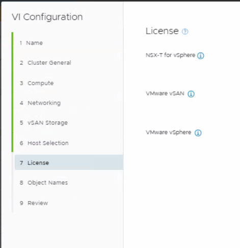
Put in your license keys
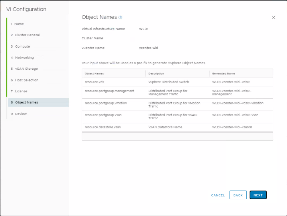
Check the object names
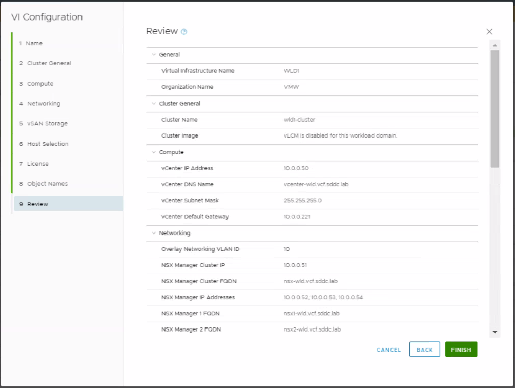
Review the final configuration
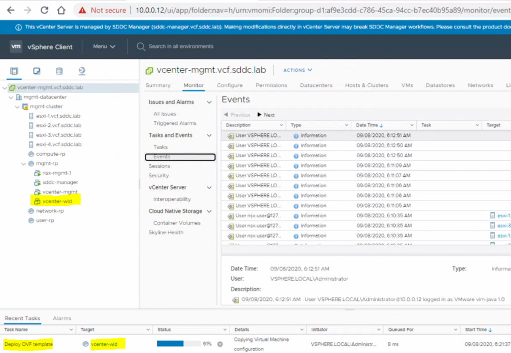
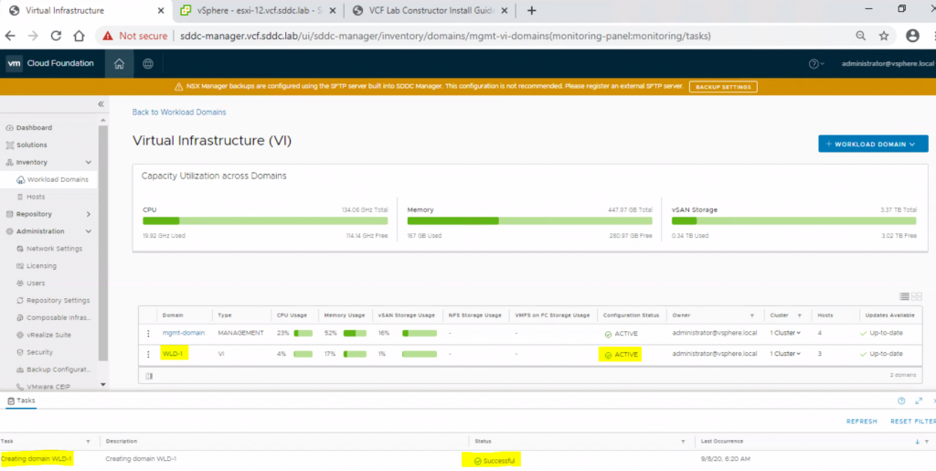
You will start to see the vcenter-wld appliance being deployed
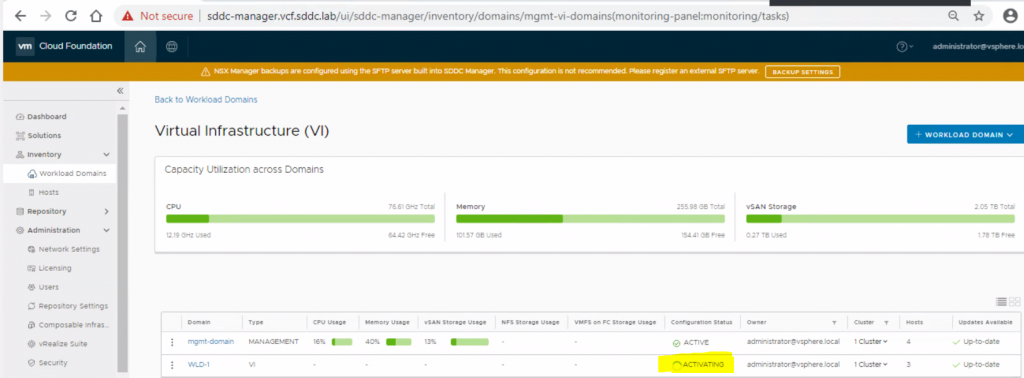
You will see the workload domain activating
When it is finally done, we should see the following
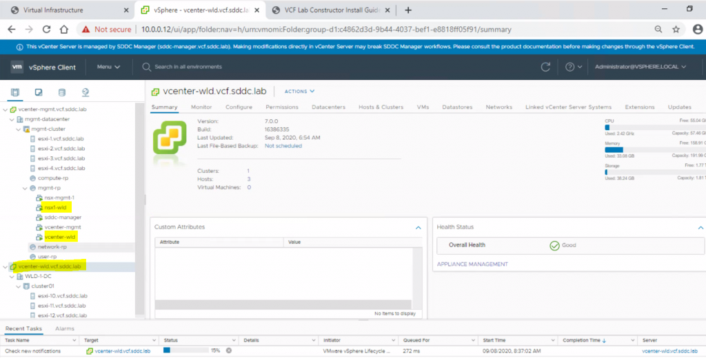
If we log out of the vCenter and back in then we will see the linked mgmt and workload vCenters under one page
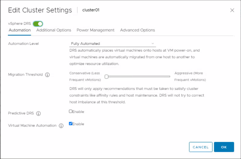
Edit the cluster settings and change the migration threshold to Conservative
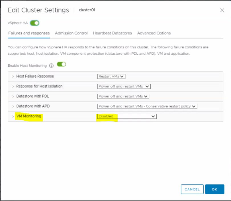
In the HA settings, set the VM monitoring to disabled.
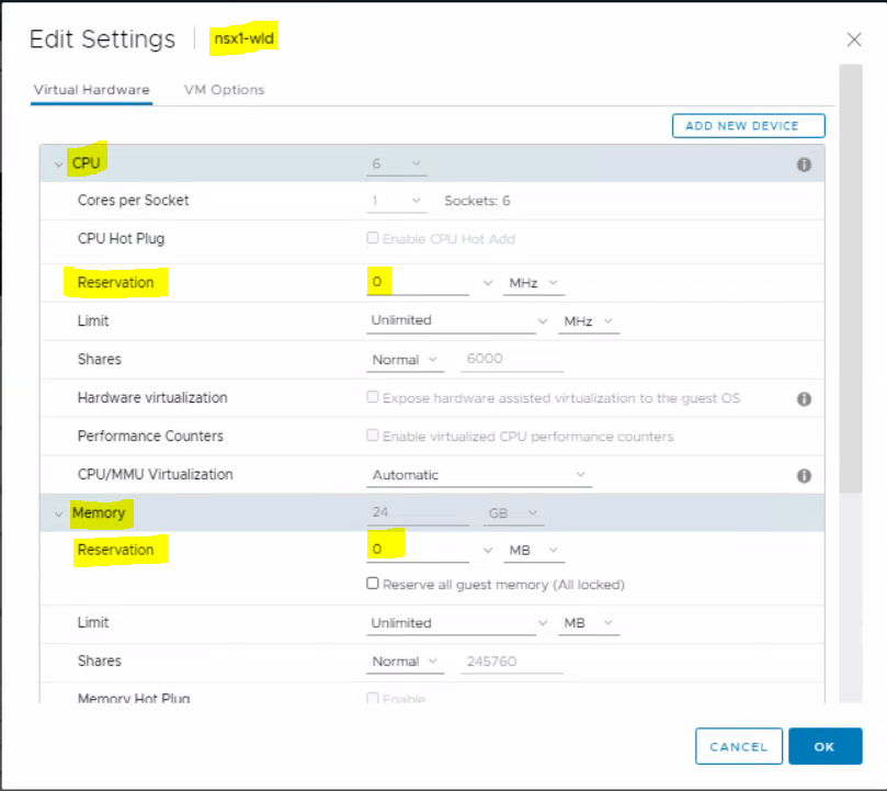
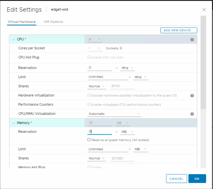
Edit the settings on the nsx1-wld to change the CPU and memory reservation to 0
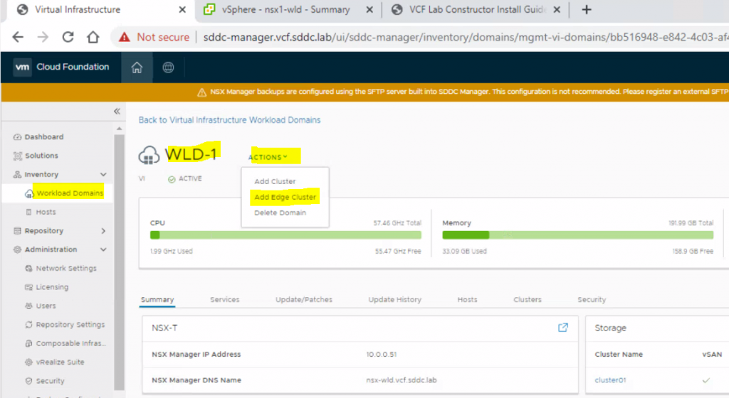
In the sddc-manager.vcf.sddc.lab > Workload Domains > WLD-1 – Actions – Add Edge Cluster
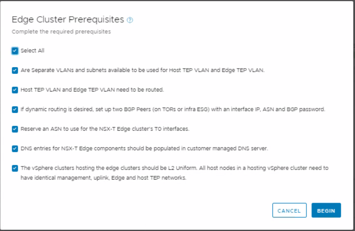
Select All on the Edge Cluster Prerequisites page
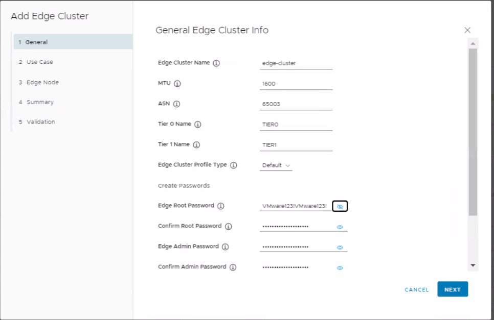
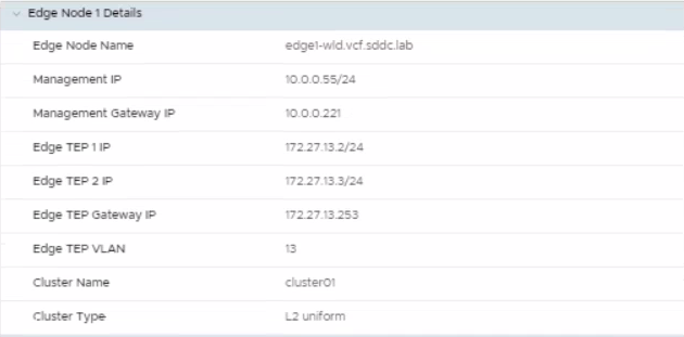
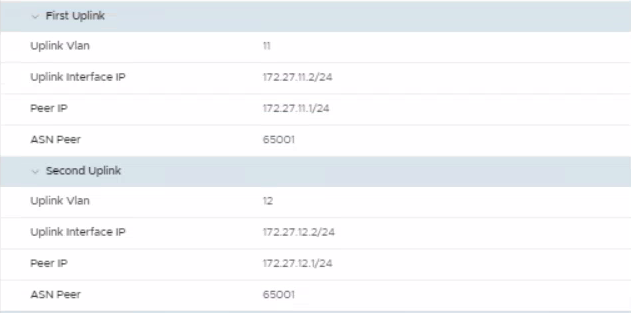
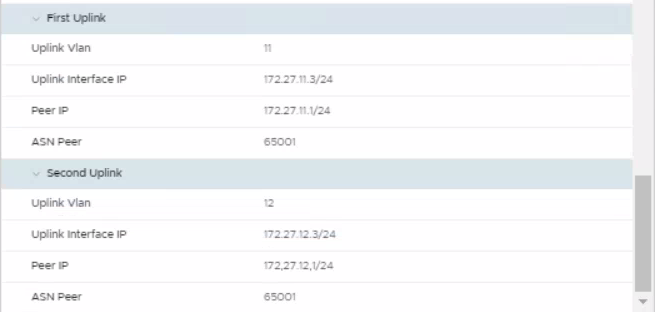
Put in the Edge Cluster details (I followed this from the lab guide
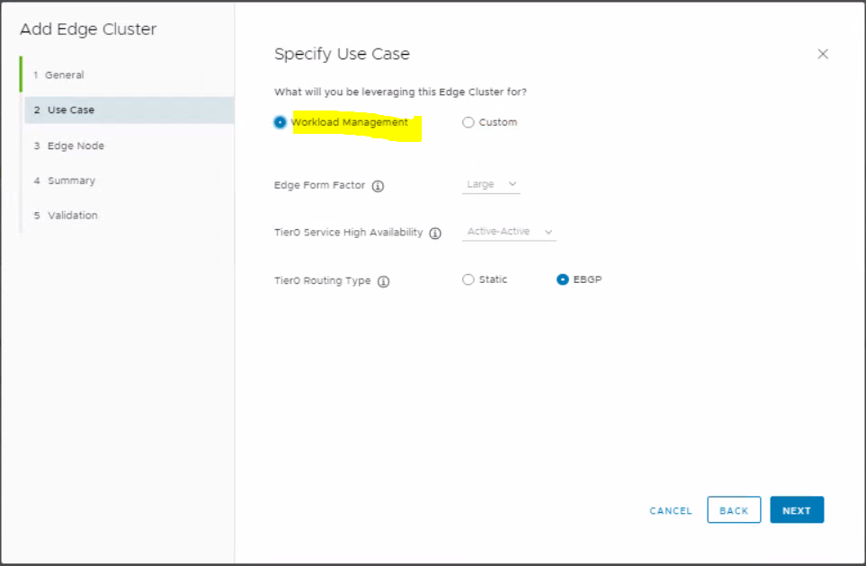
Select Workload domain on the specify use case
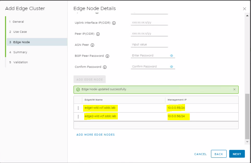
Next, add the first Edge node, once you have filled everything in, select the button to add the second edge node
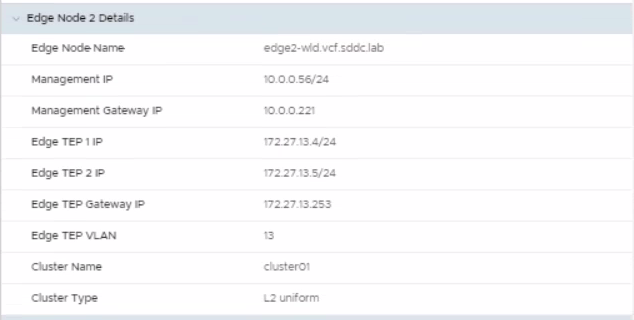
Add the second Edge node and click Add Edge node
Once complete, you should see that both Edge nodes are added successfully
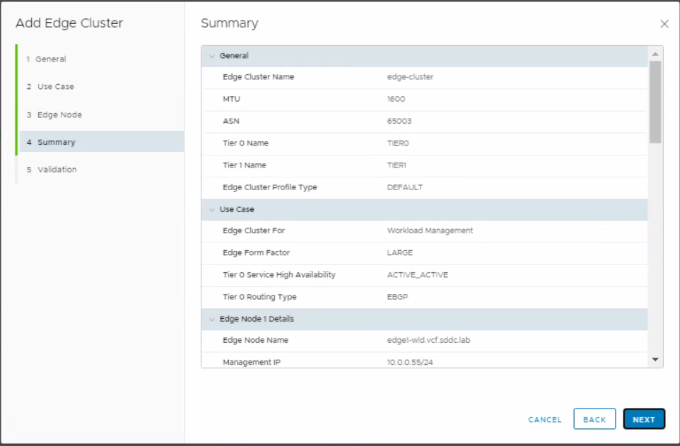
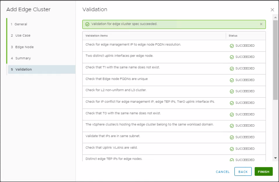
On the Summary page, double check all your details are correct and click Next
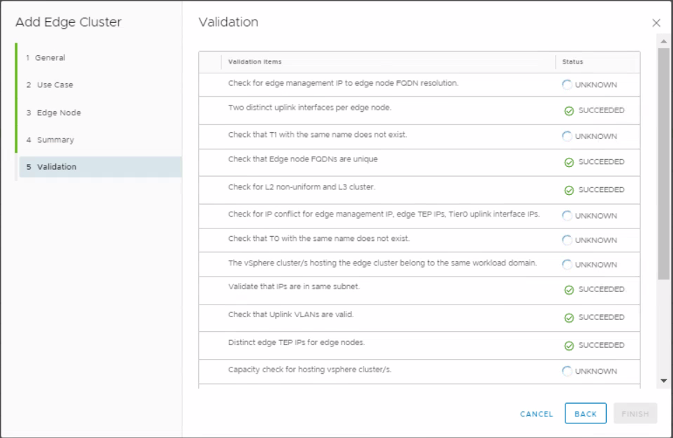
Validation will run
Validation should succeed
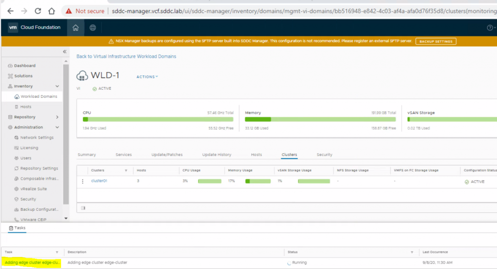
Click Finish and check out SDDC Manager where you should see a task saying Adding edge cluster
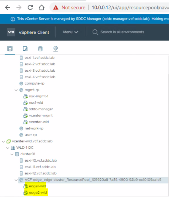
You will see the Edge servers deploying in vCenter if you check
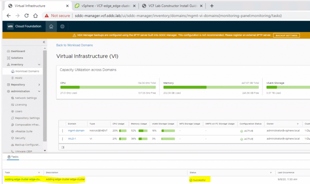
When complete it should say succcesful
In the vCenter, edit the settings for both edge1-wld and edge2-wld to change the CPU shares to normal and the memory reservation to 0
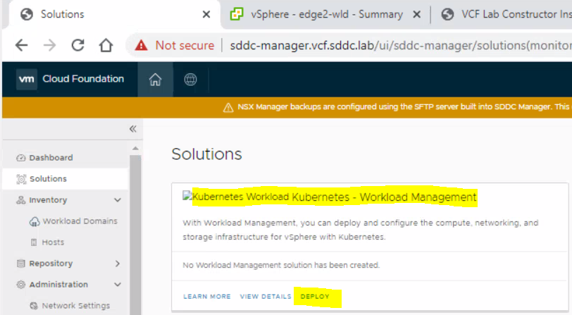
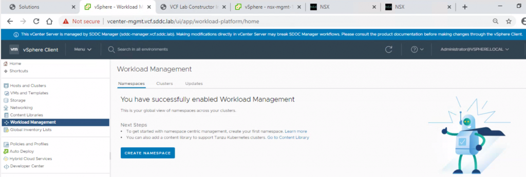
Go to the SDDC Dashboard and select Solutions and Deploy Kubernetes Workload Kubernetes – Workload Management.
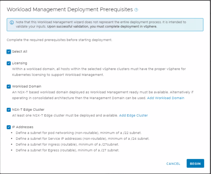
Read the Pre-requisites and select all.
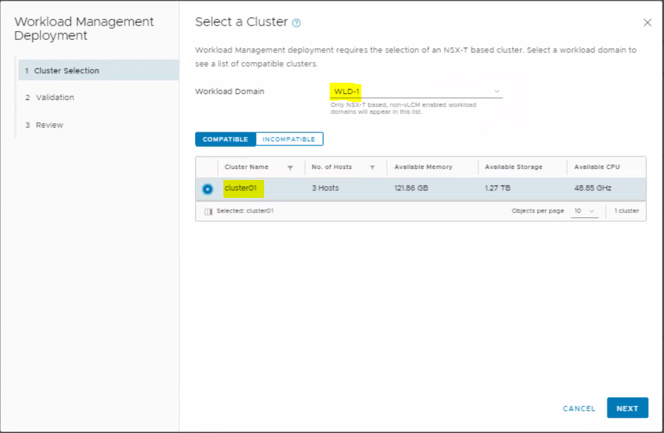
Select Workload domain, then cluster01 and next
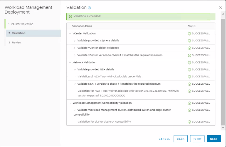
It will then go through a process of validation
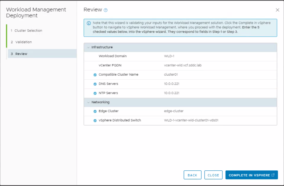
Read the Review page and click Complete in vSphere
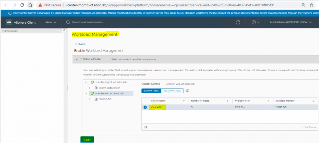
In vcenter-wld.vcf.sddc.lab > Workload Management > Select cluster01 and click Next
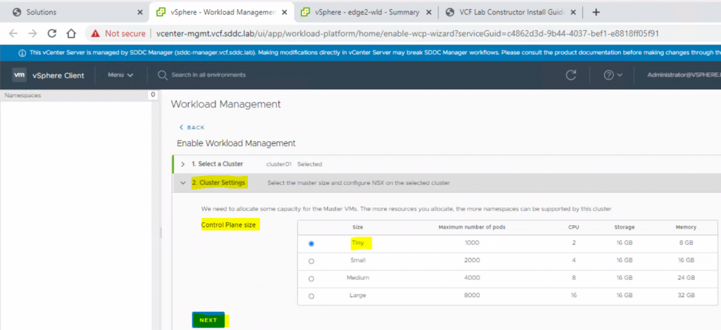
Select Tiny and click Next
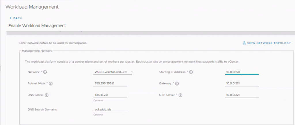
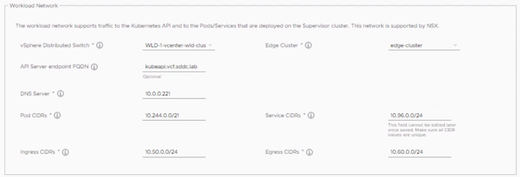
Enter network info and click next
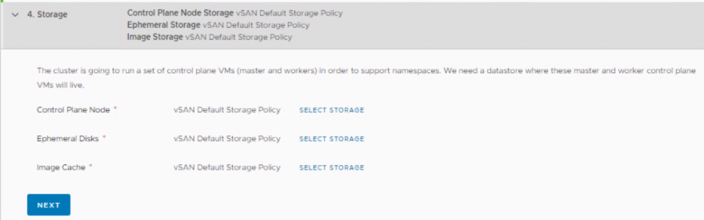
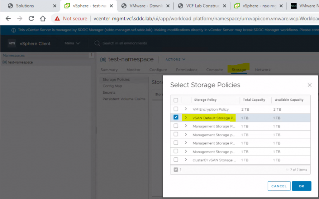
Select storage policy for each component
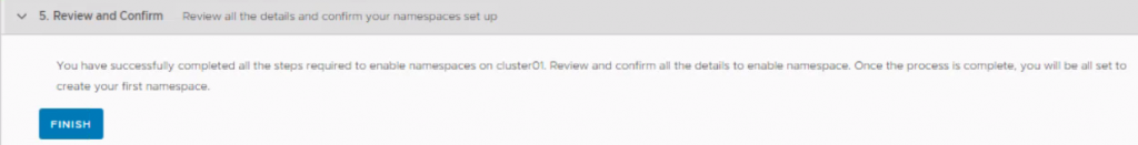
Review and Confirm
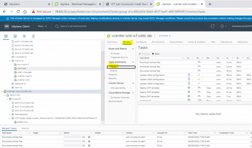
In vcenter-wld.vcf.sddc.lab, you can monitor the tasks
The below actions then take place
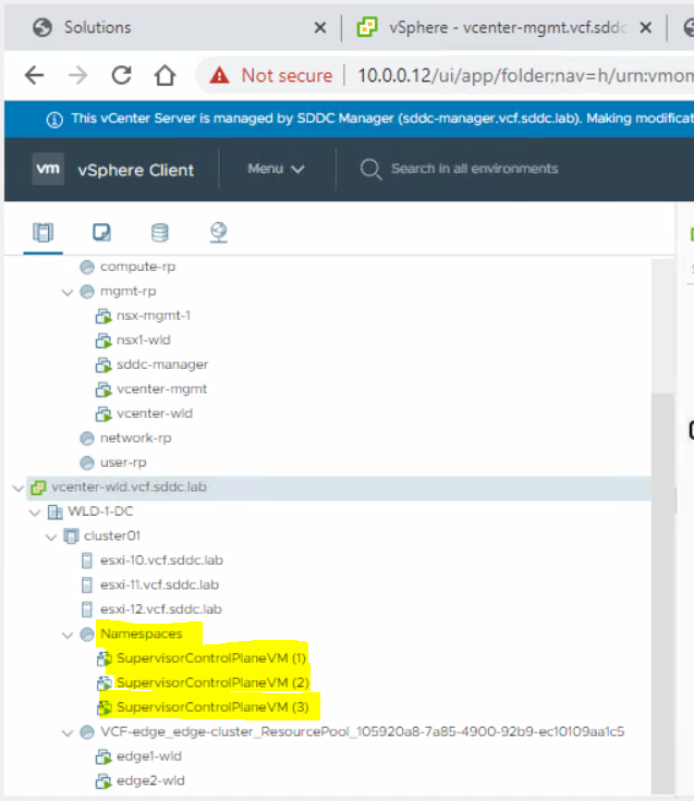
The deployment of 3 x Supervisor Control Plane VMs
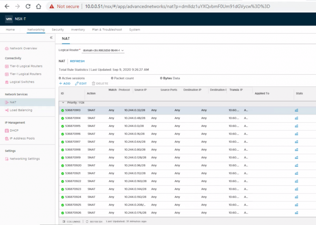
The creation of a set of SNAT rules (Egress) in NSX-T for a whole array of K8s services
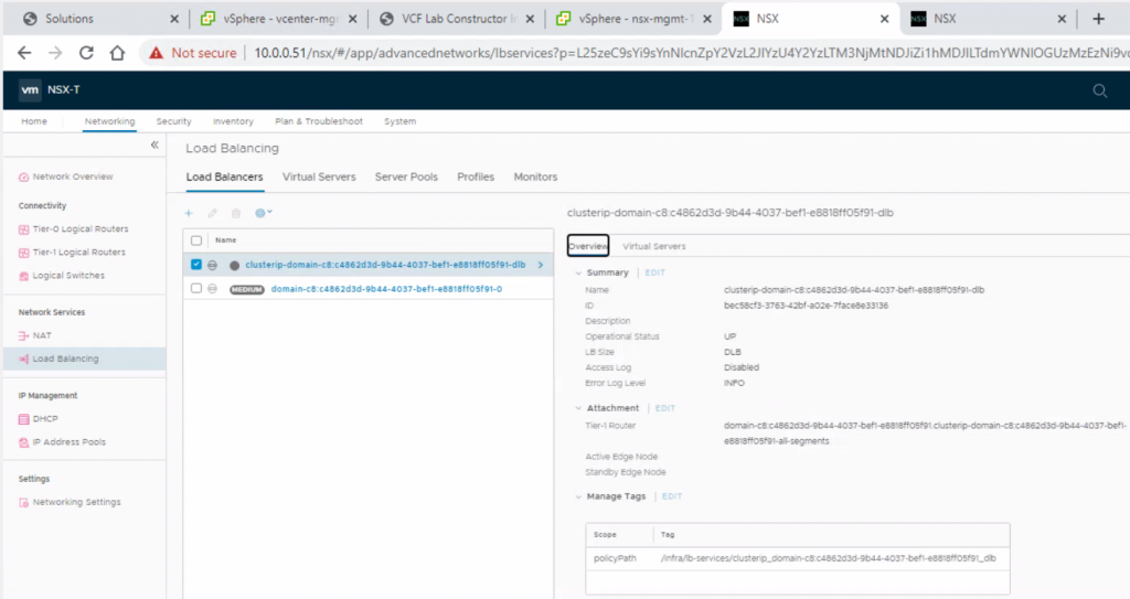
The creation of a Load Balancer (Ingress) in NSX-T for the K8s control plane
The installation of the Spherelet on the ESXi hosts so that they behave as Kubernetes worker nodes
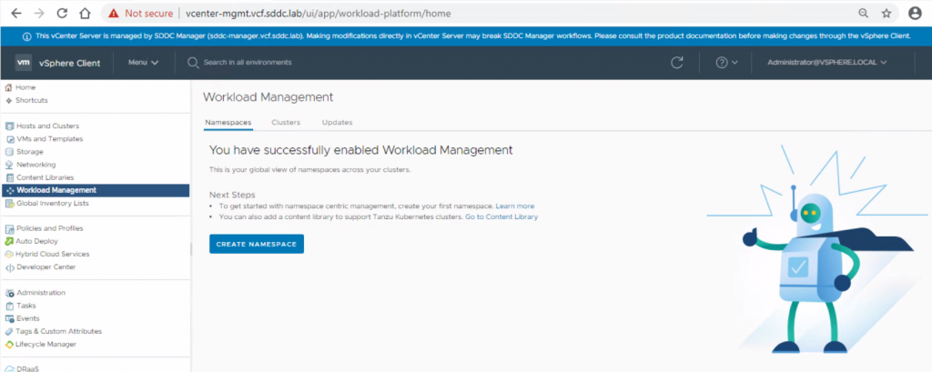
In vCenter, we can see that Workload Management has been succesfully created
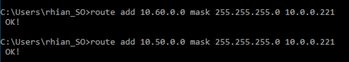
Add 2 routes to the jump host
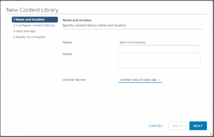
We now need to create a content library
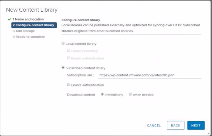
Select subscribed content library and click Next
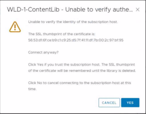
Accept the certificate
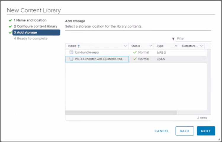
Select vSAN datastore and click Next
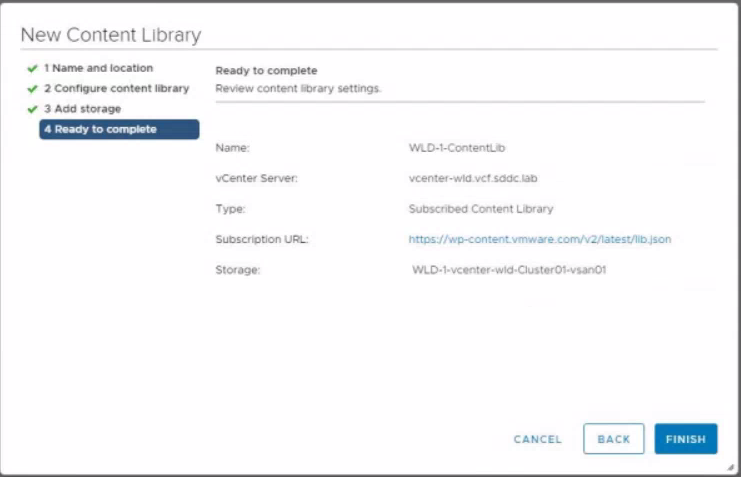
Click Finish
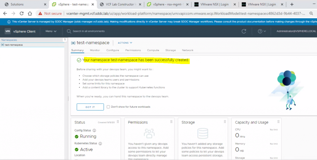
Go to vCenter > Home > Workload management > Create Namespace
I created a namespace called test-namespace
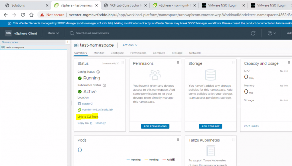
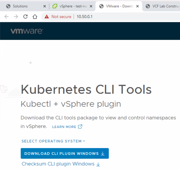
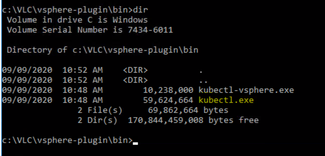
Download the kubectl plugin from the CLI Tools link. If you click on Open
You will get this page. Click Download CLI plugin and unzip it. I unzipped mine to c:\VLC\vsphere-plugin
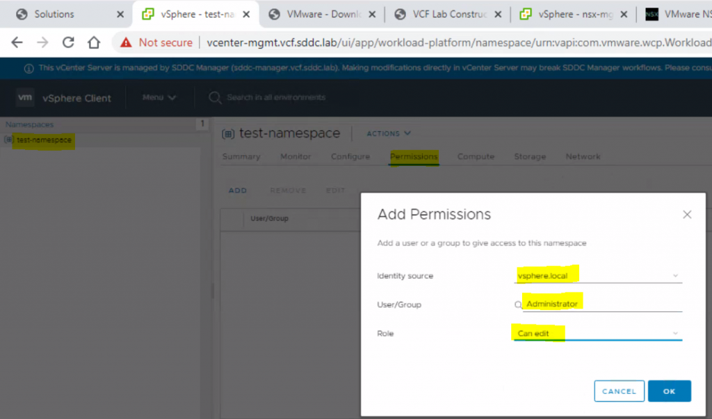
Create permissions on the name space
Set Storage Policies
Open Command prompt, Navigate to c:\VLC\vsphere-plugin\bin
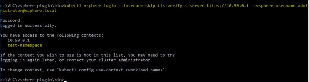
Login as administrator@vsphere.local to 10.50.0.1 which is just the first IP address of the ingress CIDR block you provided which is assigned to the load balancer in NSX that then points to the supervisor cluster
This is where I need to read up more on Kubernetes and vCloud in general to do anything else! 😀
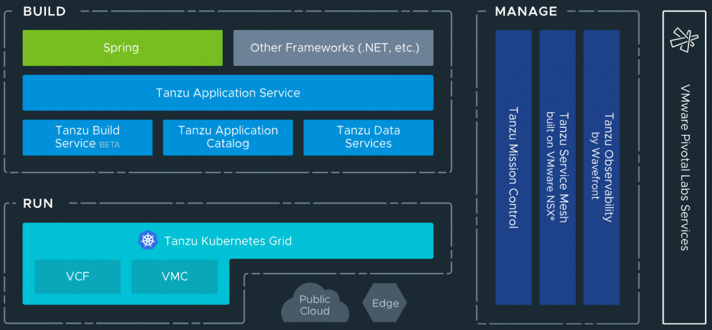
VMware Tanzu is a portfolio of services for modernizing Kubernetes controlled container-based applications and infrastructure.
Application services: Modern application platforms
Build service: Container creation and management. Heptio, Bitnami and Pivotal come under this category. Bitnami packages and delivers 180+ Kubernetes applications, ready-to-run virtual machines and cloud images. Pivotal controls one of the most popular application frameworks, “Spring”, and offers customers the Pivotal Application Service recently announcing that PAS and its components, Pivotal Build Service and Pivotal Function Service are being evolved to run on Kubernetes.
Application catalogue: Production ready, open source containers
Data services: Cloud native data and messaging including Gemfire, RabbitMQ and SQL
Kubernetes grid. Enterprise ready runtime
Mission Control: Centralised cluster management
Observability: Modern app monitoring and analytics
Service mesh: App wide networking and control
VMware Tanzu services
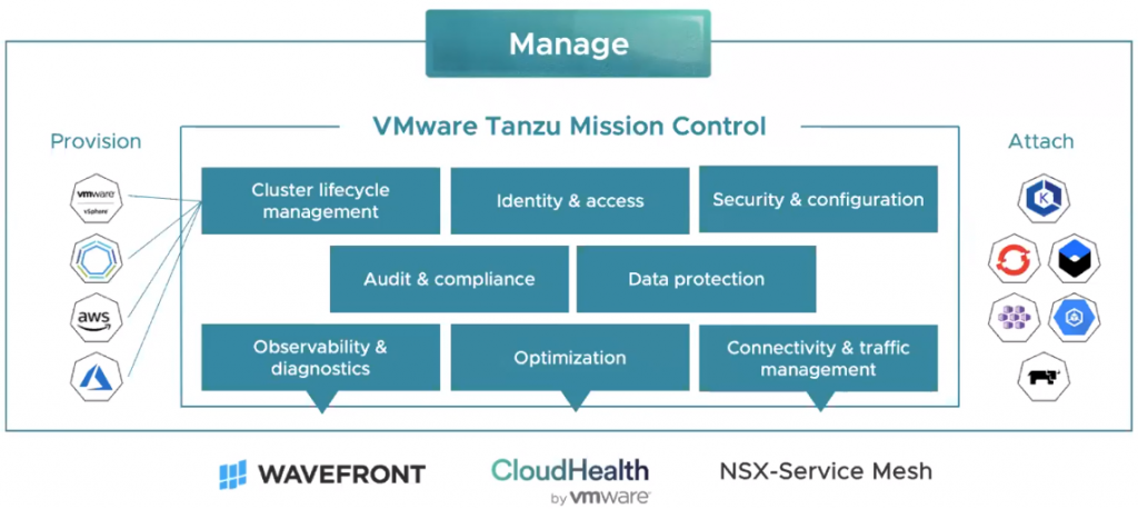
What isTanzu Mission Control?
VMware Tanzu Mission Control is a SaaS based control plane which allows customers to manage all the Kubernetes clusters, across vSphere, VMware PKS, public clouds, managed services, packaged distributions from a central single point of control and single pane of glass. This will allow applying policies for access, quotas, back-up, security and more to individual clusters or groups of clusters. It will support a wide array of operations such as life-cycle management including initial deployment, upgrade, scale and delete. This will be achieved via the open source Cluster API project.
As these environments evolve, there can be a proliferation of containers and applications so how do you keep this all under control allowing the developers to do their jobs and operations to keep the infrastructure under control to help with the following
Map enterprise identity to Kubernetes RBAC across clusters
Define policies once and push them across clusters
Manage cluster lifecycle consistently
Unified view of cluster metrics, logs and data
Cross cluster cloud data
Automated policy controlled cross cluster traffic
Monitor Kubernetes costs
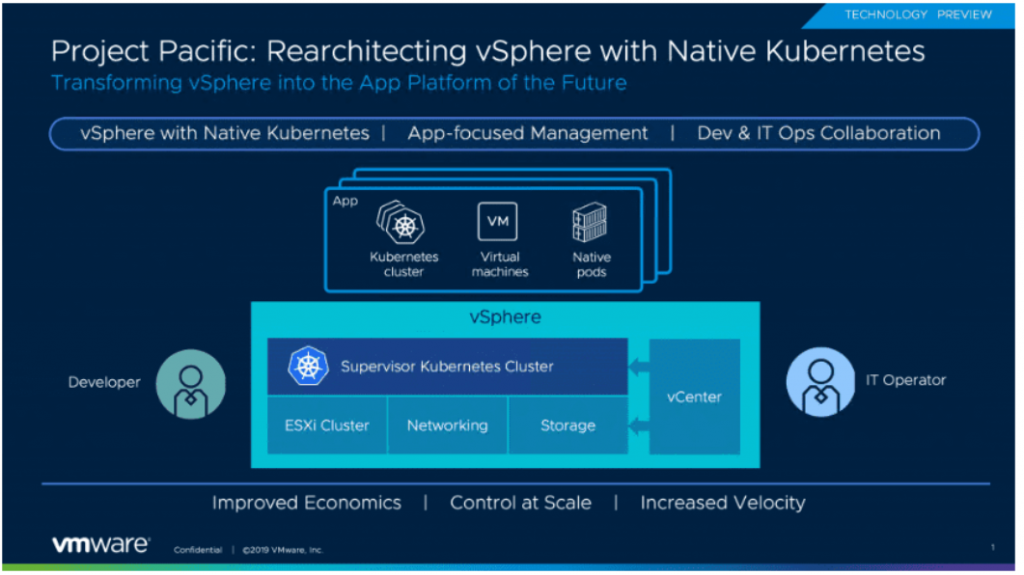
What is Project Pacific?
Project Pacific is an initiative to embed Kubernetes into the control plane of vSphere for managing Kubernetes workloads on ESXi hosts. The integration of Kubernetes and vSphere will happen at the API and UI layers, but also the core virtualization layer where ESXi will run Kubernetes natively. A developer will see and utilise Project Pacific as a Kubernetes cluster and an IT admin will still see the normal vSphere infrastructure.T
The control plane will allow the deployment of
Virtual Machines and cluster of VMs
Kubernetes Clusters
Pods
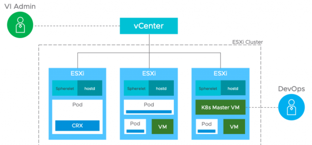
The Supervisor cluster
The control plane is made up of a supervisor cluster using ESXi as the worker nodes instead of Linux. This is carried out by by integrating a Spherelet directly into ESXi. The Spherelet doesn’t run in a VM, it runs directly on ESXi. This allows workloads or pods to be deployed and run natively in the hypervisor, alongside normal Virtual Machine workloads. A Supervisor Cluster can be thought of as a group of ESXi hosts running virtual machine workloads, while at the same time acting as Kubernetes worker nodes and running container workloads.
vSphere Native Pods
The supervisor cluster allows workloads or pods to be deployed. Native pods are actually containers that comply with the Kubernetes Pod specification. This functionality is provided by a new container runtime built into ESXi called CRX. CRX optimises the Linux kernel and hypervisor and removes some of the traditional heavy config of a virtual machine enabling the binary image and executable code to be quickly loaded and booted. The Spherelet ensures containers are running in pods. Pods are created on a network internal to the Kubernetes nodes. By default, pods cannot talk to each other across the cluster of nodes unless a Service is created. A Service in Kubernetes allows a group of pods to be exposed by a common IP address, helping define network routing and load balancing policies without having to understand the IP addressing of individual pods
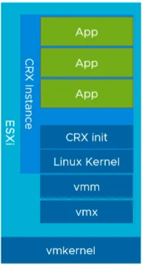
CRX – Container runtime for ESXi
Each virtual machine has a vmm (virtual machine manager) and vmx (virtual machine executive) process that handles all of the other subprocesses to support running a VM. To implement Kubernetes, VMware introduced a new process called CRX (the container runtime executive) which manages the processes associated with a Kubernetes Pod. Each ESXi server also runs the equivalent of hostd (the ESXi scheduler) called spherelet, analogous to the kubelet in standard Kubernetes.
A CRX instance is a specific form of VM which is packaged with ESXi and provides a Linux Application Binary Interface (ABI) through a very isolated environment. VMware supply the Linux Kernel image used by CRX instances. When a CRX instance is brought up, ESXi will push the Linux image directly into the CRX instance. Since it is pretty much concentrated down from a normal VM, most of the other features have been removed and you can launch it in less than a second.
CRX instances have a CRX init process which provides the endpoint with communication with ESXi and allows the environment running inside of the CRX instance to be managed
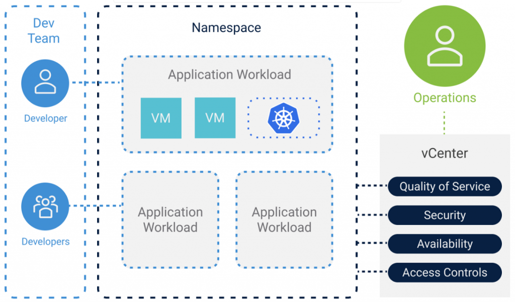
Namespaces
A Namespace in the Kubernetes cluster includes a collection of different objects like CRX VMs or VMX VMs. Namespaces are commonly used to provide multi-tenancy across applications or users, and to manage resource quotas
Guest Kubernetes Clusters
It is important to understand that the Supervisor Cluster itself does not deliver regular Kubernetes based clusters. The supervisor Kubernetes cluster is a specific implementation of Kubernetes for vSphere which is not fully conformant with upstream Kubernetes. If you want general purpose Kubernetes workloads, you have to use Guest Clusters. Guest Clusters in vSphere use the open source Cluster API project to lifecycle manage Kubernetes clusters, which in turn uses the VM operator to manage the VMs that make up a guest.
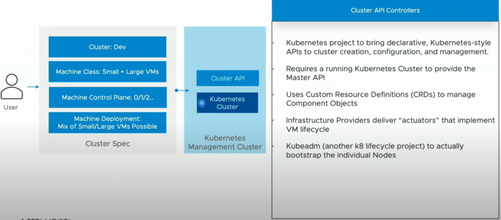
What is Cluster API?
This is an Open source project for managing the lifecycle of a Kubernetes cluster using Kubernetes itself. You start with the management cluster which gives you an API with custom resources or operators.
TPM (Trusted Platform Module) is an industry standard for secure cryptoprocessors. TPM chips are serial devices found in most of today’s desktops, laptops and servers. vSphere 6.7 supports TPM version 2.0. Physical TPM chips are secure cryptoprocessors that enhance host security by providing a trust assurance in hardware compared to software. A TPM 2.0 chip validates an ESXi host’s identity. Host validation is the process of authenticating and attesting to the state of the host’s software at a given point in time. UEFI secure boot, which ensures that only signed software is loaded at boot time, is a requirement for successful attestation. The TPM 2.0 chip records and securely stores measurements of the software modules booted in the system, which vCenter Server verifies.
What is the functionality of TPM?
Random number generator: prevents the platform from relying on software pseudo random numbers generators to generate cryptographic keys (except for the primary keys generated from seeds in 2.0.
Symmetric and asymmetric cryptographic keys generator
Encryption/decryption.
It also provides secure storage capabilities in two memory types, Volatile and NonVolatile memory (NVRAM) for the following elements:
Primary Storage Key (known as Storage Root Key in TPM 1.2). This is a root key of a key hierarchy for key derivation process and stored in persistent memory
Other entities, such as Indexes, Objects, Platform Configuration Registers (PCR), Keys, Seeds and counters.
What is vTPM?
The Virtual Trusted Platform Module (vTPM) feature lets you add a TPM 2.0 virtual cryptoprocessor to a virtual machine. A vTPM is a software-based representation of a physical Trusted Platform Module 2.0 chip.
Differences Between a Hardware TPM and a Virtual TPM
You use a hardware Trusted Platform Module (TPM) as a cryptographic coprocessor to provide secure storage of credentials or keys. A vTPM performs the same functions as a TPM, but it performs cryptographic coprocessor capabilities in software. A vTPM uses the .nvram file, which is encrypted using virtual machine encryption, as its secure storage
A hardware TPM includes a preloaded key called the Endorsement Key (EK). The EK has a private and public key. The EK provides the TPM with a unique identity. For a vTPM, this key is provided either by the VMware Certificate Authority (VMCA) or by a third-party Certificate Authority (CA). Once the vTPM uses a key, it is typically not changed because doing so invalidates sensitive information stored in the vTPM. The vTPM does not contact the CA at any time
A physical TPM is not designed for 1000’s of VM’s to store their credentials. The “Non-Volatile Secure Storage” size is tiny in kilobytes.
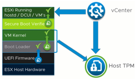
How does a physical TPM work with vCenter?
When the host boots, the host loads UEFI which checks the Boot Loader and ESXi starts loading. VMKBoot communicates with TPM and information about the host is sent to vCenter to check everything is correct.
How does a vTPM work?
The specific use case for a vTPM on vSphere is to support Windows 10 and 2016 security features.
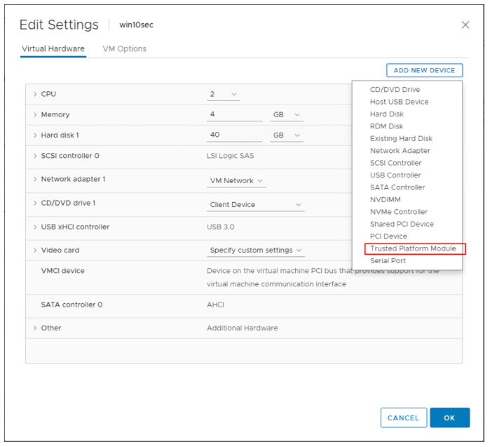
How do you add a vTPM?
You can add a vTPM to a virtual machine in the same way you add virtual CPUs, memory, disk controllers, or network controllers. A vTPM does not require a physical Trusted Platform Module (TPM) 2.0 chip to be present on the ESXi host. However, if you want to perform host attestation, an external entity, such as a TPM 2.0 physical chip, is required.
Note: If you have no KMS Server added to vCenter Server, even with a new virtual machine that has EFI and secure boot enabled, you will not see the option to add the Trusted Platform Module.
When added to a virtual machine, a vTPM enables the guest operating system to create and store keys that are private. These keys are not exposed to the guest operating system reducing the virtual machine’s attack surface. Enabling a vTPM greatly reduces this risk of compromising a guest O/S. These keys can be used only by the guest operating system for encryption or signing. With an attached vTPM, a third party can remotely attest to (validate) the identity of the firmware and the guest operating system.
You can add a vTPM to either a new virtual machine or an existing virtual machine. A vTPM depends on virtual machine encryption to secure vital TPM data. When you configure a vTPM, VM encryption automatically encrypts the virtual machine files but not the disks. You can choose to add encryption explicitly for the virtual machine and its disks.
You can also back up a virtual machine enabled with a vTPM. The backup must include all virtual machine data, including the *.nvram file which is the storage for the vTPM. If your backup does not include the *.nvram file, you cannot restore a virtual machine with a vTPM. Also, because the VM home files of a vTPM-enabled virtual machine are encrypted, ensure that the encryption keys are available at the time of a restore.
What files are encrypted and not encrypted?
The .nvram file
Parts of the VMX file
Swap, .vmss, .vmsn, namespacedb
DeployPackage (used by Guest Customization)
Log files are not encrypted.
Virtual machine requirements:
EFI firmware (Set in VM Settings > VM Options > Boot Options > Firmware
Hardware version 14
vCenter Server 6.7 or greater.
Virtual machine encryption (to encrypt the virtual machine home files).
Key Management Server (KMS) configured for vCenter Server (virtual machine encryption depends on KMS)
Windows Server 2016 (64 bit)
Windows 10 (64 bit)
Can you vMotion a machine with vTPM?
Yes, you can but Cross vCenter vMotion of an encrypted VM is not supported.
Does the host need a physical TPM to run a virtual TPM?
With vTPM, the physical host does not have to be equipped with a TPM module device. Everything is taken care of by the software by using the .nvram file to contain the contents of the vTPM hardware. The file is encrypted using virtual machine encryption and a KMS server.
Don't think about what can happen in a month. Don't think what can happen in a year. Just focus on the 24 hours in front of you and do what you can to get closer to where you want to be :-)