Archive for Objective 3 Tuning and Optimisation

Understand appropriate use cases for CPU affinity

magnet

What is CPU Affinity?

By specifying a CPU affinity setting for each virtual machine, you can restrict the assignment of virtual machines to a subset of the available processors in multiprocessor systems. By using this feature, you can assign each virtual machine to processors in the specified affinity set.

CPU affinity specifies virtual machine-to-processor placement constraints and is different from the relationship created by a VM-VM or VM-Host affinity rule, which specifies virtual machine-to-virtual machine host placement constraints.
In this context, the term CPU refers to a logical processor on a hyperthreaded system and refers to a core on a non-hyperthreaded system.

The CPU affinity setting for a virtual machine applies to all of the virtual CPUs associated with the virtual machine and to all other threads (also known as worlds) associated with the virtual machine. Such virtual machine threads perform processing required for emulating mouse, keyboard, screen, CD-ROM, and miscellaneous legacy devices.

By setting a CPU affinity on the virtual machine you are limiting the available CPUs on which the virtual machine can run. It does not dedicate that CPU to that virtual machine and therefore does not restrict the CPU scheduler from using that CPU for other virtual machines

Problems with CPU Affinity

In some cases, such as display-intensive workloads, significant communication might occur between the virtual CPUs and these other virtual machine threads. Performance might degrade if the virtual machine’s affinity setting prevents these additional threads from being scheduled concurrently with the virtual machine’s virtual CPUs. Examples of this include a uniprocessor virtual machine with affinity to a single CPU or a two-way SMP virtual machine with affinity to only two CPUs.

Consider your resource management needs before you enable CPU affinity on hosts using hyperthreading. For example, if you bind a high priority virtual machine to CPU 0 and another high priority virtual machine to CPU 1, the two virtual machines have to share the same physical core. In this case, it can be impossible to meet the resource demands of these virtual machines. Ensure that any custom affinity settings make sense for a hyperthreaded system

For the best performance

When you use manual affinity settings, VMware recommends that you include at
least one additional physical CPU in the affinity setting to allow at least one of the virtual machine’s threads to be scheduled at the same time as its virtual CPUs. Examples of this include

  • A uniprocessor virtual machine with affinity to at least two CPUs
  • A two-way SMP virtual machine with affinity to at least three CPUs

Assign a Virtual Machine to a Specific Processor
Using CPU affinity, you can assign a virtual machine to a specific processor. This allows you to restrict the assignment of virtual machines to a specific available processor in multiprocessor systems.

Procedure

  • In the vSphere Client inventory panel, select a virtual machine and select Edit Settings.
  • Select the Resources tab and select Advanced CPU
  • Click the Run on processor(s) button
  • Select the processors where you want the virtual machine to run and click OK
  • If you cannot see this option, it is because the host is in a DRS Cluster, the CPU affinity “Run on processor” feature  is not availble as its the DRS that manages ressources!

affinity

Use cases for CPU Affinity

  • Cisco’s Unity

Cisco Unity messaging is a real-time application, which makes it more difficult to virtualize than traditional data-centric applications, such as database and email servers. (For example, to support 144 concurrent voice sessions, Cisco Unity messaging must place 7,200 packets on the wire at a precise 20 ms interval.) Delivering this level of performance in a reliable, predictable, and serviceable manner requires some concessions, primarily surrounding CPU Affinity

Read this article on CPU Affinity

http://frankdenneman.nl/2011/01/11/beating-a-dead-horse-using-cpu-affinity/

Create DRS and DPM Alarms

images

DRS Alarms

  • Right click the Datacenter or Cluster and Select Alarm > Add New Alarm
  • Select Clusters

DRSALARM

  • Click Triggers  > Add

drsalarm2

  • You can click Advanced and tune the alarm even more

drs4

  • Click Reporting

DRSREP

  • Click Actions and choose how to be notified

DRSACTION

DPM Alarms

You can use event-based alarms in vCenter Server to monitor vSphere DPM.
The most serious potential error you face when using vSphere DPM is the failure of a host to exit standby mode when its capacity is needed by the DRS cluster. You can monitor for instances when this error occurs by using the preconfigured Exit Standby Error alarm in vCenter Server. If vSphere DPM cannot bring a host out of standby mode (vCenter Server event DrsExitStandbyModeFailedEvent), you can configure this alarm to send an alert email to the administrator or to send notification using an SNMP trap. By default, this alarm is cleared after vCenter Server is able to successfully connect to that host.

To monitor vSphere DPM activity, you can also create alarms for the following vCenter Server events.

  • Entering Standby mode (about to power off host) DrsEnteringStandbyModeEvent
  • Successfully entered Standby mode (host power off succeeded) DrsEnteredStandbyModeEvent
  • Exiting Standby mode (about to power on the host) DrsExitingStandbyModeEvent
  • Successfully exited Standby mode (power on succeeded) DrsExitedStandbyModeEvent

Alarm setup Instructions

  • Click the Datacenter or Cluster and Select Alarms
  • Click Definitions
  • Double click on Exit Standby Error
  • Select Hosts for Alarm Type

dpm1

  • Select Triggers

DPM

  • Select Reporting

DRSREP

  • Select Actions

dpm2

  • Right click the Datacenter or Cluster and Select Alarm > Add New Alarm
  • Select Datastore Clusters

sdrs1

  • Select Triggers

sdrs2

  • Select Reporting

DRSREP

  • Select Action

DRSACTION

Great Alarm Link from the Communities

http://communities.vmware.com/servlet/JiveServlet/download/12145-1-35516/vSphere%20Alarms%20v2.xlsx

DPM Explained

index

What is DPM?

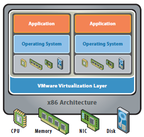
The vSphere Distributed Power Management (DPM) feature allows a DRS cluster to reduce its power consumption by powering hosts on and off based on cluster resource utilization.
vSphere DPM monitors the cumulative demand of all virtual machines in the cluster for memory and CPU resources and compares this to the total available resource capacity of all hosts in the cluster. If sufficient excess capacity is found, vSphere DPM places one or more hosts in standby mode and powers them off after migrating their virtual machines to other hosts. Conversely, when capacity is deemed to be inadequate, DRS brings hosts out of standby mode (powers them on) and uses vMotion to migrate virtual machines to them. When making these calculations, vSphere DPM considers not only current demand, but it also honors any user-specified virtual machine resource reservations.

ESXi hosts cannot automatically be brought out of standby mode unless they are running in a cluster managed by vCenter Server.

Power Management Protocols

vSphere DPM can use one of three power management protocols to bring a host out of standby mode:

  • Intelligent Platform Management Interface (IPMI)
  • Hewlett-Packard Integrated Lights-Out (iLO), or
  • Wake-On-LAN (WOL)

Each protocol requires its own hardware support and configuration. If a host does not support any of these protocols it cannot be put into standby mode by vSphere DPM. If a host supports multiple protocols, they are used in the following order: IPMI, iLO, WOL.

Configure IPMI or iLO Settings for vSphere DPM (Host First)

IPMI is a hardware-level specification and Hewlett-Packard iLO is an embedded server management technology. Each of them describes and provides an interface for remotely monitoring and controlling computers.
You must perform the following procedure on each host.

Prerequisites

  • Both IPMI and iLO require a hardware Baseboard Management Controller (BMC) to provide a gateway for accessing hardware control functions, and allow the interface to be accessed from a remote system using serial or LAN connections. The BMC is powered-on even when the host itself is powered-off. If properly enabled, the BMC can respond to remote power-on commands.
  • If you plan to use IPMI or iLO as a wake protocol, you must configure the BMC. BMC configuration steps vary according to model. See your vendor’s documentation for more information.
  • With IPMI, you must also ensure that the BMC LAN channel is configured to be always available and to allow operator-privileged commands.
  • On some IPMI systems, when you enable “IPMI over LAN” you must configure this in the BIOS and specify a particular IPMI account.
  • vSphere DPM using only IPMI supports MD5- and plaintext-based authentication, but MD2-based authentication is not supported. vCenter Server uses MD5 if a host’s BMC reports that it is supported and enabled for the Operator role. Otherwise, plaintext-based authentication is used if the BMC reports it is supported and enabled. If neither MD5 nor plaintext authentication is enabled, IPMI cannot be used with the host and vCenter Server attempts to use Wake-on-LAN.

Instructions to Configure BMC from UEFI

(Alternatively, you may configure IPMI by pressing Ctrl + E during boot)

During these steps, remember to record the IP address and MAC address of the BMC.

  • Power on the host
  • Enter the Unified Server Configurator (UEFI v2.1) by pressing F10 (System Services) at boot
  • After the application start, select Configuration Wizards
  • Select iDRAC Configuration
  • Enable IPMI Over LAN, click Next
  • Enter a Host Name String that aligns with the ESXi host name, click Next
  • Enter a unique IP Address and the details of your network, click Next
  • Optionally configure IP6, click Next
  • Click Next at the Virtual Media Configuration screen
  • At the LAN User Configuration screen, we configured an account and password, click Next
  • At the summary screen, click Apply
  • Click Finish, Back, Exit and Reboot

Configure Wake On LAN

  • Power on the host
  • Press Ctrl + S to Enter Broadcom Comprehensive Configuration Management
  • Select the adapter to be used for WOL
  • Select MBA Configuration
  • Enable Pre-boot Wake On LAN
  • Press Escape, Escape, Save and Exit
  • Repeat steps 3 – 6 for any other adapters
  • Press Escape

Configure IPMI/iLO for vSphere 5

Note: This may only be done from a connection to vCenter. This is a feature that relies upon DRS.

  • Press Ctrl + Shift + H to enter the Host and Cluster View from within vSphere Client
  • Select the Host to enable IPMI/iLO (You should configure IPMI/iLO on all hosts in your cluster)
    3.Click the Configuration Tab > Software > Power Management
    4.Click Properties
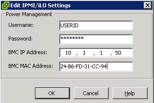
    5.Enter the Username, Password, IP Address, and MAC Address
  • First you may need to log into IPMI, ILO or WOL and obtain the IP and MAC Address
  • Log into vCenter
  • Select a host
  • Select Configuration
  • Select Power Management
  • Click Properties
  • Enter the following information.
  • User name and password for a BMC account. (The user name must have the ability to remotely power the host on.)
  • IP address of the NIC associated with the BMC, as distinct from the IP address of the host. The IP address should be static or a DHCP address with infinite lease.
  • MAC address of the NIC associated with the BMC.

DPM

  • Click OK.

Configure Wake on LAN Settings for vSphere DPM (Host First)

The use of Wake-on-LAN (WOL) for the vSphere DPM feature is fully supported, if you configure and successfully test it according to the VMware guidelines. You must perform these steps before enabling vSphere DPM for a cluster for the first time or on any host that is being added to a cluster that is using vSphere DPM.

Prerequisites

Before testing WOL, ensure that your cluster meets the prerequisites.

  • Your cluster must contain at least two ESX 3.5 (or ESX 3i version 3.5) or later hosts.
  • Each host’s vMotion networking link must be working correctly. The vMotion network should also be a single IP subnet, not multiple subnets separated by routers
  • The vMotion NIC on each host must support WOL. To check for WOL support, first determine the name of the physical network adapter corresponding to the VMkernel port by selecting the host in the inventory panel of the vSphere Client, selecting the Configuration tab, and clicking Network Adapters

wol

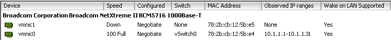
  • The Wake On LAN Supported column for the relevant adapter should show Yes.
  • To display the WOL-compatibility status for each NIC on a host, select the host in the inventory panel o the vSphere Client, select the Configuration tab, and click Network Adapters. The NIC must show Yes in the Wake On LAN Supported column.
  • The switch port that each WOL-supporting vMotion NIC is plugged into should be set to auto negotiate the link speed, and not set to a fixed speed (for example, 1000 Mb/s). Many NICs support WOL only if they can switch to 100 Mb/s or less when the host is powered off.
  • After you verify these prerequisites, test each ESXi host that is going to use WOL to support vSphere DPM.
  • When you test these hosts, ensure that the vSphere DPM feature is disabled for the cluster
  • CAUTION Ensure that any host being added to a vSphere DPM cluster that uses WOL as a wake protocol is tested and disabled from using power management if it fails the testing. If this is not done, vSphere DPM might power off hosts that it subsequently cannot power back up.

Procedure

  • Click the Enter Standby Mode command on the host’s Summary tab in the vSphere Client.
  • This action powers down the host.
  • Try to bring the host out of standby mode by clicking the Power On command on the host’s Summary tab.
  • Observe whether or not the host successfully powers back on.
  • For any host that fails to exit standby mode successfully, select the host in the cluster Settings dialog box’s Host Options page and change its Power Management setting to Disabled.
  • After you do this, vSphere DPM does not consider that host a candidate for being powered off.

Enabling vSphere DPM for a DRS Cluster

After you have performed configuration or testing steps required by the wake protocol you are using on each host, you can enable vSphere DPM.
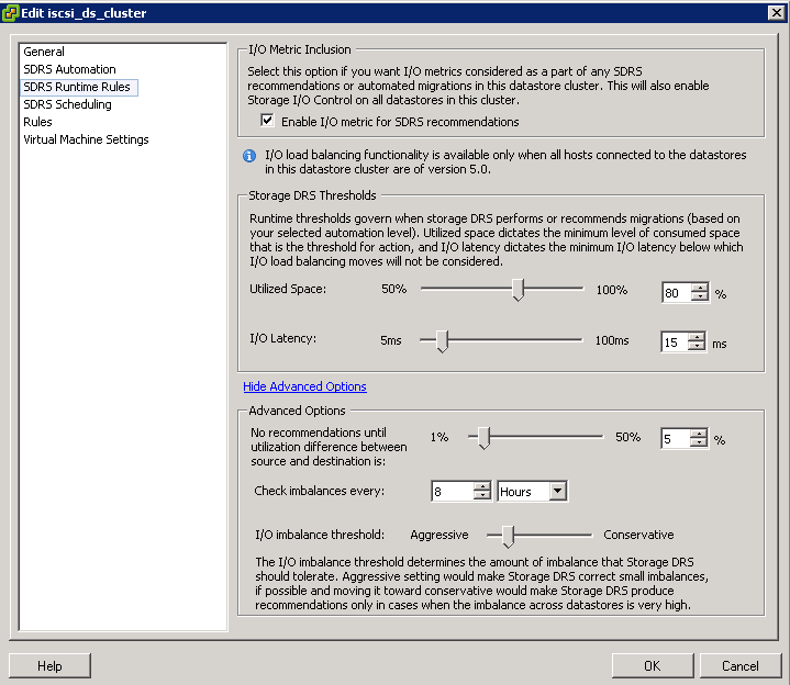
Configure the power management automation level, threshold, and host-level overrides. These settings are configured under Power Management in the cluster’s Settings dialog box.

If a host in your DRS cluster has USB devices connected, disable DPM for that host. Otherwise, DPM might turn off the host and sever the connection between the device and the virtual machine that was using it.

Instructions

  • Right click the cluster and select Edit Settings
  • Select Power Management

DPM

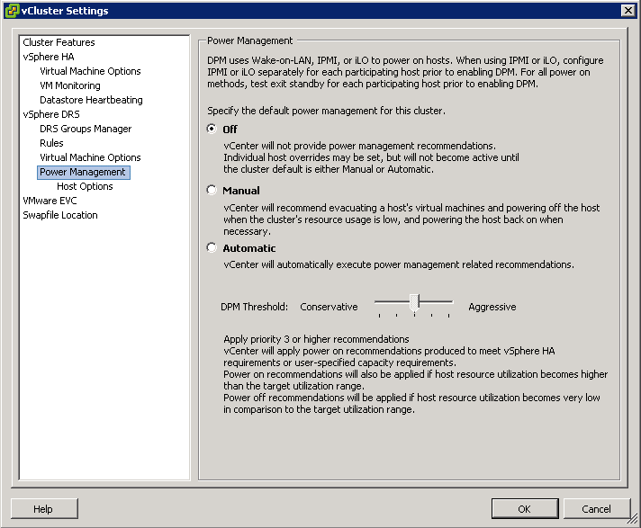
  • These priority ratings are based on the amount of over- or under-utilization found in the DRS cluster and the improvement that is expected from the intended host power state change. A priority-one recommendation is mandatory, while a priority-five recommendation brings only slight improvement.
  • The DRS threshold and the vSphere DPM threshold are essentially independent. You can differentiate the aggressiveness of the migration and host-power-state recommendations they respectively provide

Host-Level Overrides

When you enable vSphere DPM in a DRS cluster, by default all hosts in the cluster inherit its vSphere DPM automation level.
You can override this default for an individual host by selecting the Host Options page of the cluster’s Settings dialog box and clicking its Power Management setting. You can change this setting to the following options:

  • Disabled
  • Manual
  • Automatic

NOTE: Do not change a host’s Power Management setting if it has been set to Disabled due to failed exit standby mode testing.

DPM2

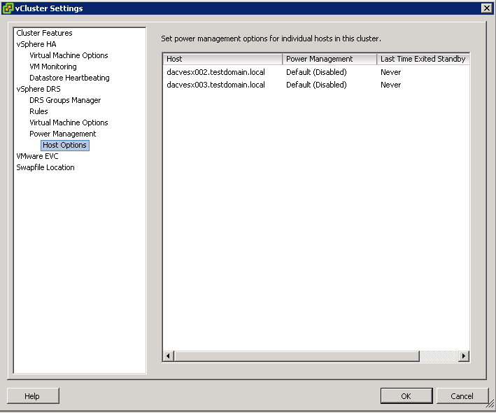
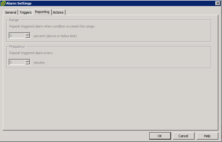
  • After enabling and running vSphere DPM, you can verify that it is functioning properly by viewing each host’s Last Time Exited Standby information displayed on the Host Options page in the cluster Settings dialog box and on the Hosts tab for each cluster. This field shows a timestamp and whether vCenter Server Succeeded or Failed the last time it attempted to bring the host out of standby mode. If no such attempt has been made, the field displays Never.

NOTE: Times for the Last Time Exited Standby text box are derived from the vCenter Server event log. If this log is cleared, the times are reset to Never.

Power Management Techniques

After VMware DPM has determined the number of hosts needed to handle the load and to satisfy all relevant constraints and VMware DRS has distributed virtual machines across the hosts in keeping with resource allocation constraints and objectives, each individual powered-on host is free to handle power management of its hardware. For CPU power management, ESX 3.5 and 4 place idle CPUs in C1 halt state. ESX 4 also has support for host-level power-saving mechanisms through changing ACPI P-states; also known as dynamic voltage and frequency scaling (DVFS). DVFS runs CPUs at a lower speed and possibly at a lower voltage when there is sufficient excess capacity where the workload will not be affected. DVFS is “off” by default but can be turned on by setting the Power.CpuPolicy advanced option to “dynamic” for the hardware that supports it. Host-level power management is synergistic with VMware DPM. Even though it can provide additional power savings beyond VMware DPM, it cannot save as much power as VMware DPM does by powering hosts down completely.

vSphere DPM Powers off the host when the cluster load is low

  • DPM considers a 40 minute load history
  • Migrates all VMs to other hosts

vSphere DPM powers on the host when the cluster load is high

  • DPM considers a 5 minute load history
  • Wake up packets are sent to the host which boots up
  • DRS initiates and some VMs are migrated to this host

VMware DPM Operation

The goal of VMware DPM is to keep the utilization of ESX hosts in the cluster within a target range, subject to the constraints specified by the VMware DPM operating parameters and those associated with VMware HA and VMware DRS. VMware DPM evaluates recommending host power-on operations when there are hosts whose utilization is above this range and host power-off operations when there are hosts whose utilization is below it. Although this approach might seem relatively straightforward, there are key challenges that VMware DPM must overcome to be an effective power-saving solution. These include the following:

  • Accurately assess workload resource demands. Overestimating can lead to less than ideal power savings. Underestimating can result in poor performance and violations of VMware DRS resource-level SLAs.
  • Avoid powering servers on and off frequently, even if running workloads are highly variable. Powering servers on and off too often impairs performance because it requires superfluous VMotion operations.
  • React rapidly to sudden increase in workload demands so that performance is not sacrificed when saving power.
  • Select the appropriate hosts to power on or off. Powering off a larger host with numerous virtual machines might violate the target utilization range on one or more smaller hosts.
    • Redistribute virtual machines intelligently after hosts are powered on and off by seamlessly leveraging VMware DRS.

VMware DPM is run as part of the periodic VMware DRS invocation (every five minutes by default), immediately after the core VMware DRS cluster analysis and rebalancing step is complete. VMware DRS itself may recommend host power-on operations, if the additional capacity is needed as a prerequisite for migration recommendations to honor VMware HA or VMware DRS constraints, to handle user requests involving host evacuation (such as maintenance mode), or to place newly powered-on virtual machines.

Evaluating Utilization

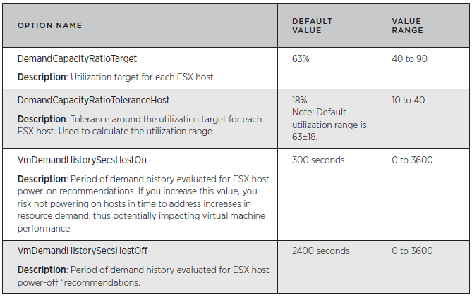
VMware DPM evaluates the CPU and memory resource utilization of each ESX host and aims to keep the host’s resource utilization within a target utilization range. VMware DPM may take appropriate action when the host’s utilization falls outside the target range. The target utilization range is defined as:

Target resource utilization range = DemandCapacityRatioTarget ± DemandCapacityRatioToleranceHost
By default, the utilization range is 45% to 81% (that is, 63% ±18%)

DPM3

Each ESX host’s resource utilization is calculated as demand/capacity for each resource (CPU and memory). In this calculation, demand is the total amount of the resource needed by the virtual machines currently running on the ESX host and capacity is the total amount of the resource currently available on the ESX host. A virtual machine’s demand includes both its actual usage and an estimate of its unsatisfied demand, to account for cases in which the demand value is constrained by the ESX host’s available resources. If an ESX host faces heavy contention for its resources, its demand can exceed 100 percent. VMware DPM computes actual memory usage using a statistical sampling estimate of the virtual machine’s working set size. It also computes the estimate of unsatisfied demand for memory using a heuristic technique.

VMware DPM calculates an ESX host’s resource demand as the aggregate demand over all the virtual machines running on that host. It calculates a virtual machine’s demand as its average demand over a historical period of time plus two standard deviations (capped at the virtual machine’s maximum demand observed over that period). Using a virtual machine’s average demand over a period of time, rather than simply its current demand, is intended to ensure that the demand used in the calculation is not anomalous. This approach also smoothes out any intermediate demand spikes that might lead to powering hosts on and off too frequently. The default period of time VMware DPM evaluates when it calculates average demand that may lead to host power-on recommendations is the past 300 seconds (five minutes). When it calculates average demand for host power-off recommendations, the default period of time VMware DPM evaluates is the past 2400 seconds (40 minutes). The default time period for evaluating host power-on recommendations is shorter because rapid reactions to power on hosts are considered more important than rapid reactions to power off hosts. In other words, providing the necessary resources for workload demands has a higher priority than saving power.

If any host’s CPU or memory resource utilization during the period evaluated for host power-on recommendations is above the target utilization range, VMware DPM evaluates powering hosts on. If any host’s CPU and any host’s memory resource utilization over the period evaluated for host power-off recommendations is below the target utilization range and there are no recommendations to power hosts on, VMware DPM evaluates powering hosts off.
In addition, when VMware DPM runs VMware DRS in what-if mode to evaluate the impact of host power-on and power-off, CPU and memory reservations are taken into account (as well as all other cluster constraints). VMware DRS will reject proposed host power-off recommendations that will violate reservations and VMware DRS will initiate host power-on operations to satisfy reservations.

Useful Link

http://www.vmware.com/files/pdf/Distributed-Power-Management-vSphere.pdf

Compare and contrast physical and virtual hardware resources

Before Virtualisation

  • Single O/S Image per machine
  • Software and Hardware tightly coupled
  • Running multiple applications on the same machine can create conflicts
  • Underutilised resources
  • Inflexible and costly infrastructure
  • Datacenter space taken up in multiple physical servers
  • High Management, Support and Operating costs

Physical

After Virtualisation

  • Hardware independence of operating system and applications
  • Virtual machines can be provisioned to any system
  • Can manage OS and application as a single unit by encapsulating them into virtual machines
  • Power Savings
  • Rack space savings
  • Feature rich flexibility (vMotion, Storage vMotion, DRS, HA)
  • Rapidly provision test and development servers

Virtual

Virtual Infrastructure now

While virtualization has been a part of the IT landscape for decades, it is only recently (in 1998) that VMware delivered the benefits of virtualization to industry-standard x86-based platforms which now form the majority of desktop, laptop and server shipments. A key benefit of virtualisation is the ability to run multiple O/S’s on a single virtual system and share the underlying hardware resource

There are 2 types of architecture – Hosted architecture (VMware Workstation) and Bare metal Architecture (ESX/ESXi)

We can now take advantage of features such as

  • The latest generation of x86-based systems feature processors with 64-bit extensions supporting very large memory capacities. This enhances their ability to host large, memory-intensive applications, as well as allowing many more virtual machines to be hosted by a physical server deployed within a virtual infrastructure.
  • The VMKernel runs individual VMMs for each VM responsible for the execution of the VM
  • The VMM which is a thin layer providing virtual x86 hardware to the overlying O/S including memory management, CPU scheduling, networking and storage
  • Hardware Assist (Intel VD and AMD V)
  • Paravirtualisation hardware
  • DirectPath
  • Direct Memory Access
  • AMD RVI and Intel EPT
  • Emulated Hardware
  • DRS
  • HA
  • sDRS
  • I/O Control for Networking and Storage
  • NPIV
  • Passthrough devices
  • Shares, Reservations and Limits
  • Resource Pools
  • Clustered file system VMFS
  • Raw Disk Mappings
  • 3 Virtual Disk types (Eager zeroed thick, Lazy Zeroed thick and Thin)
  • Memory reclamation techniques

Storage DRS

What is Storage DRS?

Virtual machine provisioning has traditionally imposed some operational challenges. Monitoring datastore capacity and I/O load has proven to be very difficult and is often neglected. The datastores used to host virtual disks for new virtual machines are often randomly selected, leading to hot spots and over- or under-utilized datastores. A new feature in vSphere 5.0, Storage DRS provides smart virtual machine placement and load balancing mechanisms based on I/O utilization and storage capacity.

Storage DRS can

  • Manage the storage resources comparable to how DRS manages compute resources in a cluster.
  • Enable smart and rapid placement of new virtual machines disk files and load balancing of existing workload
  • Storage vMotion VMs based on storage capacity, I/O latency and IOPS load
  • Be configured in Manual or Automated Modes
  • Use Affinity and Anti-Affinity rules
  • Use of fully automated Storage Maintenance Mode to clear a LUN for maintenance

Capture

Migration Recommendations

  • When the IOPs Response time is exceeded
  • When the space utilisation threshold is exceeded
  • Space utilisation is checked every 5 minutes
  • IOPS load history is checked every 8 hours
  • Load balancing is based on IOPs workload to ensure that no datastore exceeds a particular VMKernel I/O latency level

Storage DRS utilizes vCenter Server’s datastore utilization reporting mechanism to make recommendations for migrations whenever the configured utilized space threshold (default of 80% utilized) is exceeded. Storage DRS evaluates I/O load every 8 hours. The default configured maximum I/O latency threshold is 15ms. To avoid being caught by peak load issues, Storage DRS generates migration recommendations only when an imbalance persist for a long period of time (several hours out of the evaluation period)

It will take at least 16 hours of I/O Statistics before sDRS will make recommendations.

Configuration of sDRS Settings

sDRS Automation

sdrsauto

sDRS Runtime Rules

sdrsruntime

sDRS Scheduling

sdrssched

sDRS Rules for Affinity/Anti-Affinity

srdsaffin

sDRS VM Settings

sdrsvm

vSphere Storage DRS Demo

http://www.youtube.com/watch?v=FmVTY3_SQRw

Properly size a Virtual Machine based on application workload

images

Considerations

  • Make sure you know whether the Application is multithreaded or single threaded in order to select the correct amount of CPUs
  • Make sure you know whether you should be adding RDMs or VMFS VMDKs. E.g Microsoft Clustering
  • Java, Oracle and SQL Applications are very good at taking all the memory they are assigned and trying to manage it themselves. Be especially careful with Java which does not mix well with Ballooning and Paging
  • Start off small and work upwards in terms of resources. Assigning huge resources can interfere with Cluster and DRS calculations
  • Use the fastest network adapter you can for the O/S. VMXNET3 preferably to take advantage of all the new features
  • If using FT, use Thick Provisioned Eager Zeroed disks.
  • Decide where to place the VM swap file
  • Decide on Reservations, Limits and Shares if required
  • Check the Manufacturers recommendations for setting any advanced attributes
  • Use correctly raided storage. E.g RAID5, RAID10 etc
  • Choose the Disk Mode – Independent and Dependent

Modify Large Page Settings

TOOL

Modify Large Page Settings

VMware ESXi Server supports the use of large pages inside virtual machines. The large‐page support enables server applications to establish large‐page memory regions. Memory address translations use translation lookaside buffers (TLB) inside the CPU. The use of large pages can potentially increase TLB access efficiency and thus improve program performance.

Large pages improve the performance of many applications, but misuse of large pages may also hurt performance in some situations. The potential for performance degradation is a result of the fact that the number of large TLB entries is usually smaller than the number of small TLB entries. If the working set of an application is scattered over a wide range of address space, the application is likely to experience thrashing of a relatively small number of large TLB entries. This thrashing may result in worse overall performance with higher TLB miss rates.

Configuring Large Page Settings on the Host

  • Click on your host
  • Click the Configuration tab
  • Click Advanced Settings under Software
  • Select LPage

LargePage

LargePage

Configuring Large Page Settings on the O/S

Consult the documentation for your operating system for details on how to configure large page support

Enabling Large Page Support in Applications

Consult the documentation for your application for details on how to configure large page support. For example, the Oracle Database Platform Guide has details on how to enable large page support for an Oracle database

VMware Document on Large Pages

http://www.vmware.com/files/pdf/large_pg_performance.pdf

Identify pre-requisites for Hot-Add Features

images

What is Hot-Add?

Hot add options allow configuration changes to a virtual machine while it is powered on. Hot add options can be turned on or off for memory and number of CPU configurations for eligible virtual machines.

Hotadd

Pre-Requisites

  • You must disable CPU hot add if you plan to use USB device passthrough from an ESX/ESXi host to a virtual machine.
  • When you configure multi-core virtual CPUs for a virtual machine, CPU hot Add/remove is disabled.
  • Not enabled by default.
  • Check Guest OS support
  • Memory and CPUs can be hot added (but not hot removed)
  • Enabled per VM and needs a reboot to take effect
  • Enable on templates
  • Virtual H/W v7
  • Not compatible with Fault Tolerance

Identify VMware CPU Load Balancing Techniques

clock

The VMKernel CPU scheduler is crucial to providing good performance in a consolidated environment. Most processors these days are equipped with multiple cores per processor and controlling, managing and scheduling these multi way processors is essential. It assigns execution contexts to processors

The CPU Scheduler

The CPU Scheduler has the following features

  • Schedules the vCPUs on physical CPUs
  • Enforces the proportional-share algorithm for CPU usage
  • Supports SMP VMs
  • Uses relaxed co-scheduling for SMP VMs
  • Uses NUMA
  • Processor Topology/Cache aware
  • Hyperthreading

Schedules the vCPUs on physical CPUs

The Scheduler checks physical utilisation every 2-40ms and migrates vCPUs as necessary

Enforces the proportional-share algorithm for CPU usage

When CPUs are over-committed, hosts time slice physical CPUs across all VMs where each CPU is also prioritised by resource allocation settings in terms of Shares, Reservations and Limits)

Supports SMP VMs

If a VM is configured with multiple processors then it believes that it is running on a dedicated physical multiprocessor. ESXi maintains this by using co-scheduling of the vCPUs.

Co-Scheduling is a technique for scheduling, descheduling, preempting and blocking transactions across multiple processors. Without it, vCPUs would be scheduled independently, breaking the guests assumption regarding uniform process.

The CPU Scheduler takes “Skew” into account when scheduling vCPUs. Skew is the difference in execution rates between 2 or more vCPUs in an SMP VM. The Scheduler maintains a fine grained cumulative skew value for each vCPU in a VM. Time spent in the hypervisor is excluded from the process as sometimes the operations do not benefit from being co-scheduled. The vCPU is considered to be skewed if its cumulative skew value exceeds a configurable threshold, usually a few seconds

Uses relaxed co-scheduling for SMP VMs

Relaxed Co-Scheduling refers to a technology where vCPUs have become skewed and must be co-started. When any vCPU is scheduled, it ensures that all other vCPUs that are behind will also be scheduled

The vCPUs that move too far forward are stopped and wait for the other VMs to catch up. An idle vCPU does not gather skew and is classed as if it was running normally

Uses NUMA

Please see this blog post for more information on NUMA

http://www.electricmonk.org.uk/2012/03/01/numa/

Processor Topology/Cache aware

Basically the CPU Scheduler uses Processor Topology information to calculate and optimise the placement of vCPUs on to different sockets using socket, core and logical processor information

The CPU Scheduler also takes advantage of the Shared Last Level Cache which exists within cores on the same processor. This is a memory cache that has a dedicated channel to a CPU socket bypassing the main memory bus which makes it run at the same speed of the CPU

In some situations the CPU scheduler will spread the load across all sockets and sometimes it can be beneficial to schedule all vCPus on to the same socket. Dependent on workload and over/under committed systems

Hyperthreading

The applications most likely to benefit are 3D rendering programs, heavy-duty audio/video transcoding apps, and scientific applications built for maximum multi-threaded performance. But you may also enjoy a performance boost when encoding audio files in iTunes, playing 3D games and zipping/unzipping folders. The boost in performance can be up to 30%, although there will also be situations where Hyper-Threading provides no boost at all.

Hyper-Threading is where two threads are able to run on one single-threaded core. When a thread on the core in question is stalling or in a halt state, hyper-threading enables the core to work on a second thread instead. It makes the OS think that the processor has double the number of cores, and often yields a performance improvement

Tune ESXi VM Storage Configuration

tools

Tuning Configuration

  • Use the correct virtual hardware for the VM O/S
  • Use paravirtual hardware for I/O intensive applications
  • LSI Logic SAS for newer O/S’s
  • Size the Guest O/S Queue depth appropriately
  • Make sure Guest O/S partitions are aligned
  • Know what Disk provisioning policies are best. Thick provision lazy zeroed (default), Thick provision eager zeroed and Thin provision.
  • Store swap file on a fast or SSD Datastore

swapfile

  • When deploying a virtual machine, an administrator has a choice between three virtual disk modes. For optimal performance, independent persistent is the best choice. The virtual disk mode can be modified when the VM is powered off.

storage

  • Choose VMFS or RDM Disks to use. RDM Disk generally used by clustering software.

RDM

  • Use Disk Shares to configure more fined grained resource control

vmstroage

  • In some cases large I/O requests issued by applications can be split by the guest storage driver. Changing the VMs registry settings to issue larger block sizes can eliminate this splitting thus enhancing performance. See http://kb.vmware.com/kb/9645697