Initial Requirements
- Hitchai CCI installer – RMHORC_X64
- SRM Installer – VMware-srm-8.1.1-10646916
- Hitachi SRA installer – Hitachi_Raid_Manager_SRA_Ver02.03.01
- 1 x Windows Server 2016 Primary site SRM Server
- 1 x Windows Server 2016 Secondary site SRM Server
- 1 x 50MB command device on the Primary site server
and mount to the SRM VM as a Physical mode RDM - 1 x 50MB command device on the Secondary site server
and mount to the SRM VM as a Physical mode RDM - 2 x SRM service accounts for the protected SRM server and recovery SRM server unless you want to run SRM under the Local system account
- 2 x SRM DB service accounts for the protected SRM server and recovery SRM server
- SSL certificates – https://kb.vmware.com/s/article/2085644
What is the Hitachi SRA?
Hitachi Storage Replication Adapter (SRA) is an interface that integrates
Hitachi storage systems and replication software with VMware® vCenter
SRM™ processes
What is the Hitachi CCI?
Hitachi’s remote and in-system replication software require CCI to manage
the pairs. The adapter plug-in links CCI with Site Recovery Manager.
There are two CCI components:
- Command devices, which reside on the storage systems. CCI uses the
command device as the interface to the storage system from the host. The command device accepts commands from the host and executes them on the storage system. The command device is a dedicated logical volume.
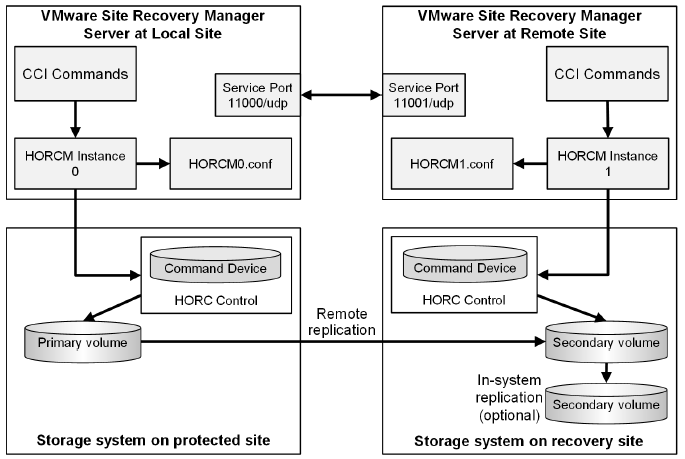
- Hitachi Open Remote Copy Manager (HORCM), which resides on the CCI server. HORCM operates as a daemon process. When activated, HORCM refers to CCI configuration definition files, also located on the server. The HORCM instance communicates with the storage system and remote servers.
HORCM definition files describe the storage systems, pair volumes, and data paths. When a user issues a command, CCI uses the information in the HORCM files to identify which volumes are the targets of the command.
Two HORCM files are needed for each pair. One file describes the primary volumes (P-VOLs), which are also referred to as “protected volumes”, and the other describes the secondary volumes (S-VOLs), which are also referred to as “recovery volumes”.
VMware SRM and Hitachi Components
Installation Steps
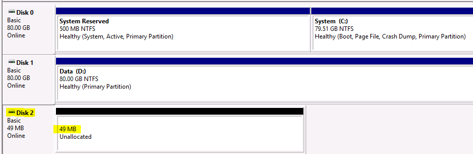
- Ask the Storage Team to present a 50MB LUN to the hosts. This will be the command device. Edit the settings of each Primary and Secondary SRM VM and add the 50MB LUN as an RDM. Log into each SRM VM and bring the disk online and initialised but not formatted
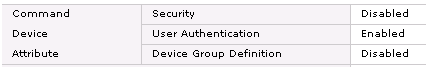
The storage team need to make sure the Command Device has the following settings on the Hitachi side or the HORCM service will not run correctly.
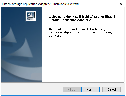
- Go to the SRM installer and Run as Administrator
- Select a language
- Click Next
- Click Next
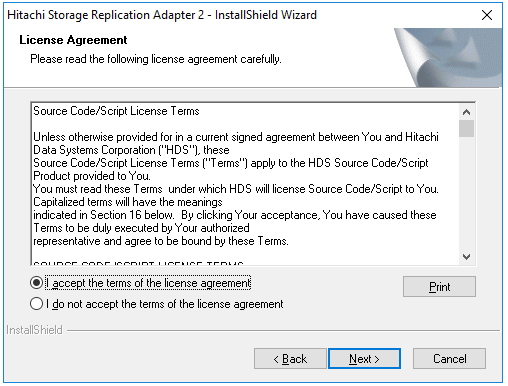
- Accept the License agreement
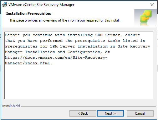
- Check Prerequisites
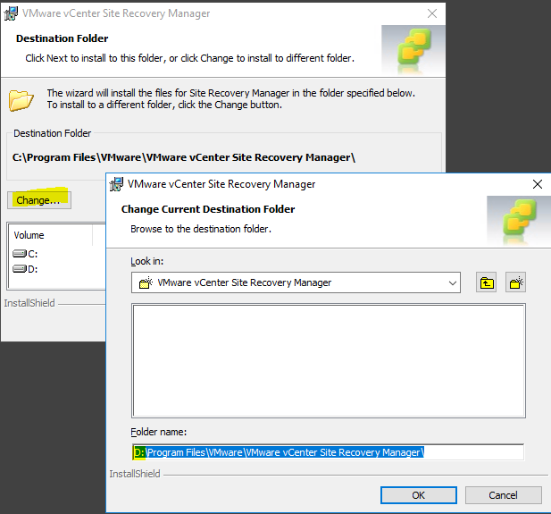
- Change the install directory if you want or leave it on the C Drive. we install ours on the D Drive
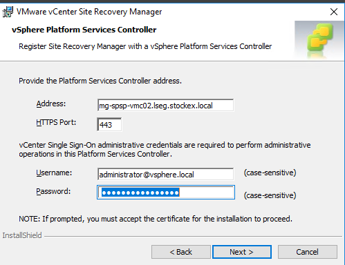
- Put in the vCenter name if you have embedded vCenters followed by administrator@vsphere.local and the password
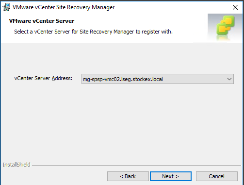
- Select a vCenter Server to register to
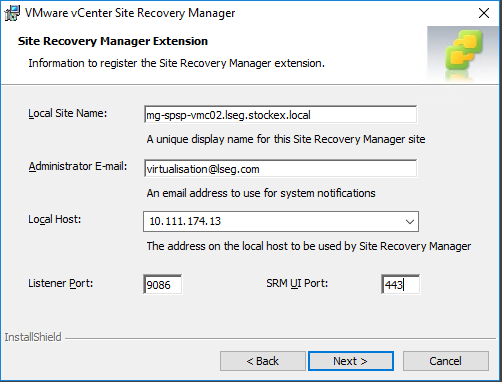
- Fill in the Site name
- Fill in an email address
- Fill in the IP address for the SRM server
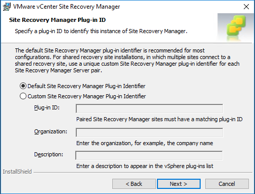
- Choose the Default Site Recovery Manager Plug-in identifier
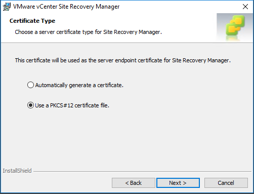
- Select what certificate to use. I have generated a PKCS#12 cert so I will use a signed certificate
- Note: When I generated the certificate through OpenSSL, I specified a password which is what you will need to enter when adding the certificate – https://kb.vmware.com/s/article/2085644
- The certificate will have a .p12 extension
- Choose the embedded option as this now supports a full installation of SRM
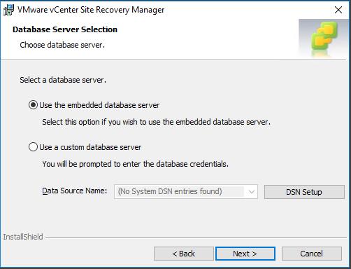
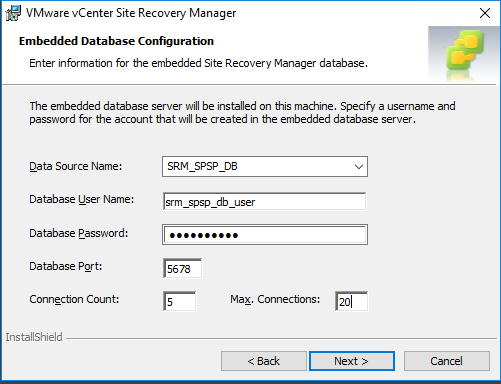
- Enter the details in the Embedded Database Configuration
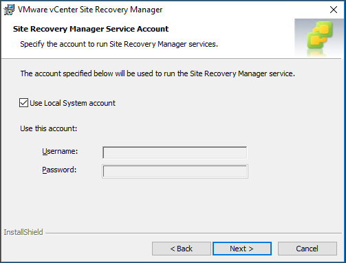
- Enter the Site Recovery Manager Service Account
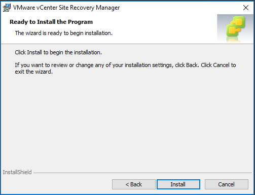
- Click Finish to start the installation
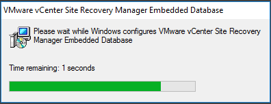
- You will see the installer creating the SRM Database
- And
- When it finishes, it should show the below screen
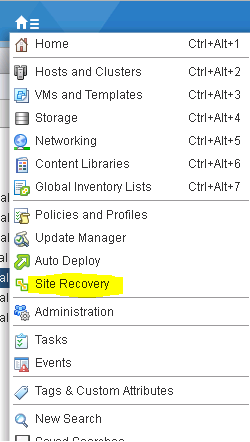
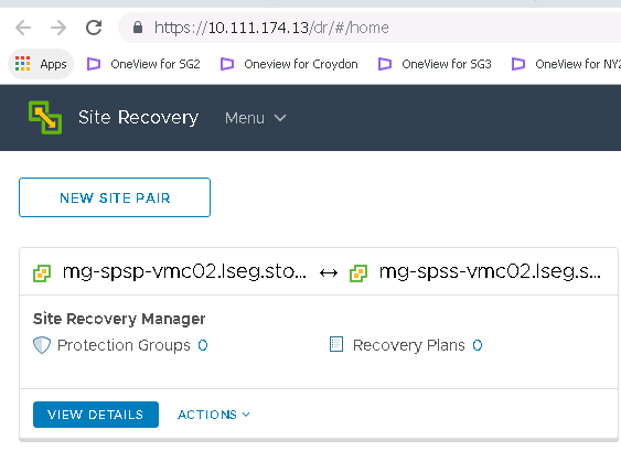
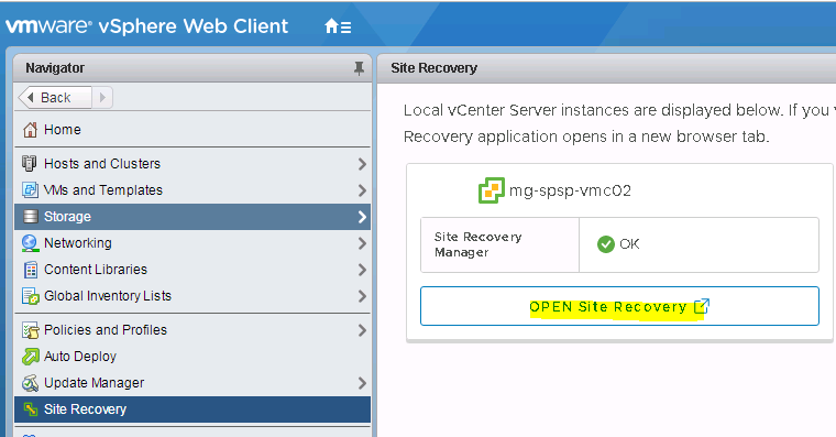
- If you log into the vCenter you should see the Site Recovery icon in the menu
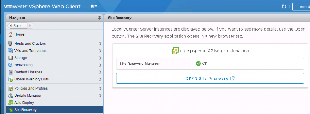
- If you click Home and select Recovery Manager, you will see the below screen.
- If you click open Site Recovery at the moment, it will ask you to sign in with SSO credentials then it will say the below message. Leave it here while we move on to installing the Recovery SRM server
- Now you need to repeat all the above install steps on the Recovery SRM Server
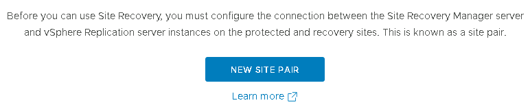
- One the Recovery SRM is complete, log into vCenter, go to site Recovery Manager and click on new Site Pair
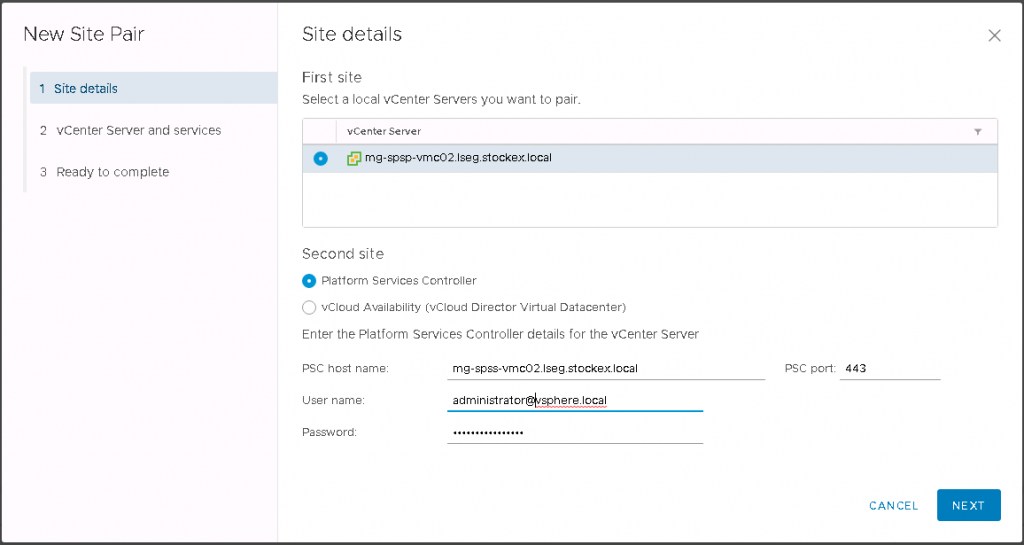
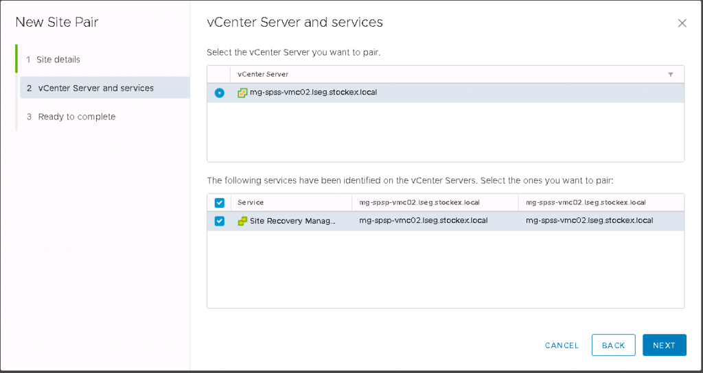
- Enter the details of the First site and Second site
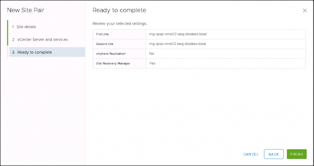
- Click next and check the details
- Click Finish to Pair the sites
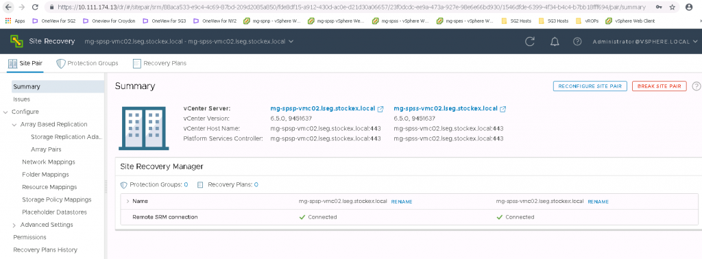
- Now you will see the below screen if it is successful
- If you now click on the View Details screen, then you will see the full details come up for the two sites
- Next we need to install the Hitachi Command Control Interface
- Note: I have already copied the software
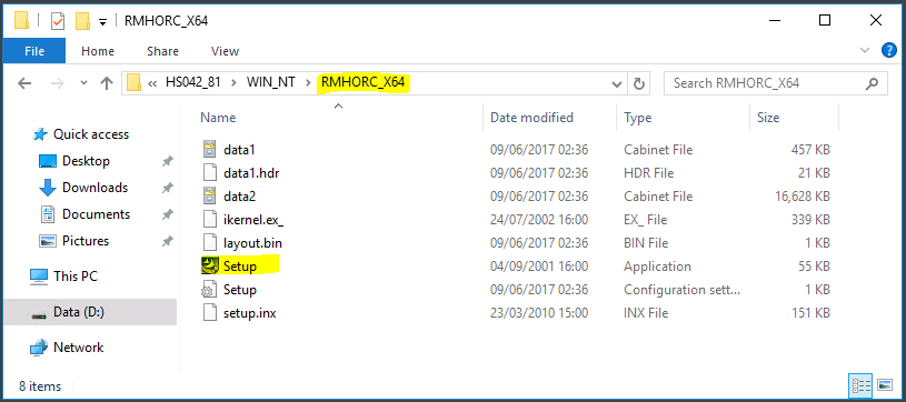
- Right click on Setup and run as Administrator
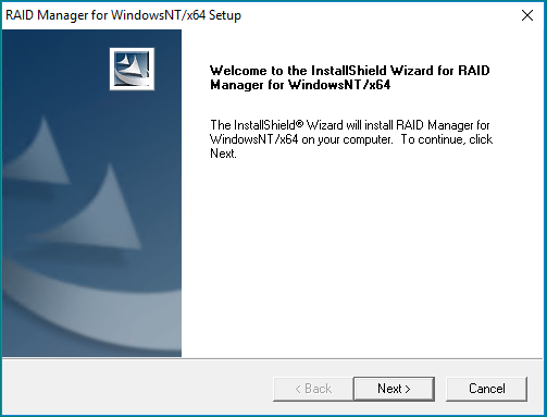
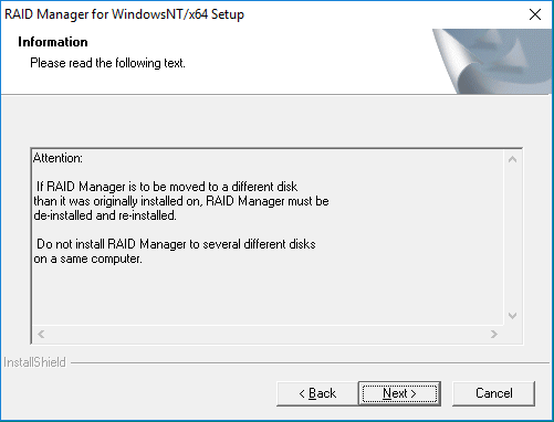
- Read the below text and click Next
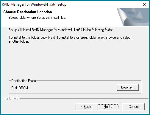
- The default installation drive is C:\HORCM. I’m installing everything on my D Drive so you’ll see the Destination folder as D:\HORCM
- The installer will run and finish

- Reboot the server
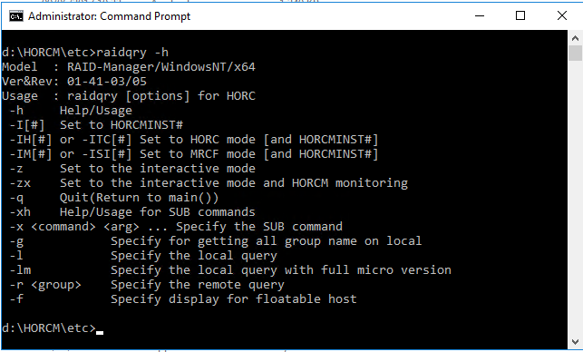
- When the server has rebooted, verify the correct version of the CCI software is running on the system by executing the below command
- D:/HORCM\etc> raidqry -h
- Install the CCI software on the recovery SRM server, reboot and check the version as per the above steps
- Next, You will need two HORCM configuration definition files to define the pair relationship: one file describes the primary volumes (P-VOLs) on the Protected SRM Server, the other file describes the secondary volumes (S-VOLs) on the Recovery SRM Server.
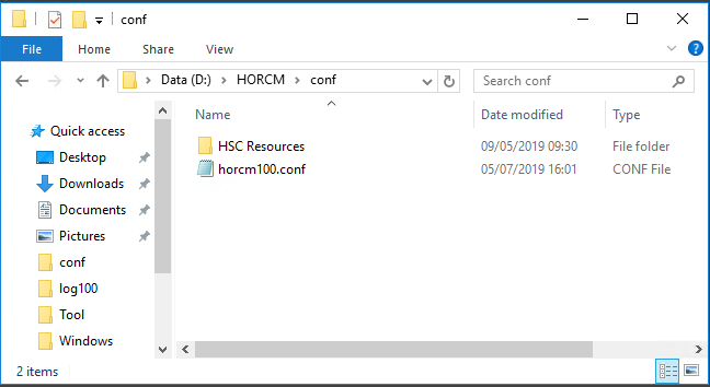
- You will need to take a copy of the default HORCM.conf file which gets installed with CCI in D:\HORCM\etc and copy it and rename it and place it in D:\HORCM\conf – Note: Just for clarity, I have named the HORCM.conf file on the Protected Server HORCM100.conf and then I’ll rename the HORCM.conf file as HORCM101.conf on the Recovery SRM Server. They must be consecutive numbers
- And the same on the Recovery site
- Open up the HORCM100.conf file and have a look at how it is structured in Notepad. Wordpad seems to lose clarity. It is quite a large file full of information (Hitachi Documentation example below) You will find the file is much larger than this and can be cut down very simply to the below
Example HORCM0.conf file from the Hitachi SRA for VMware vCenter SRM deployment guide
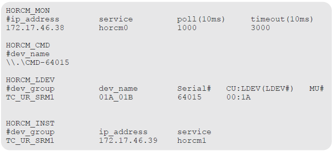
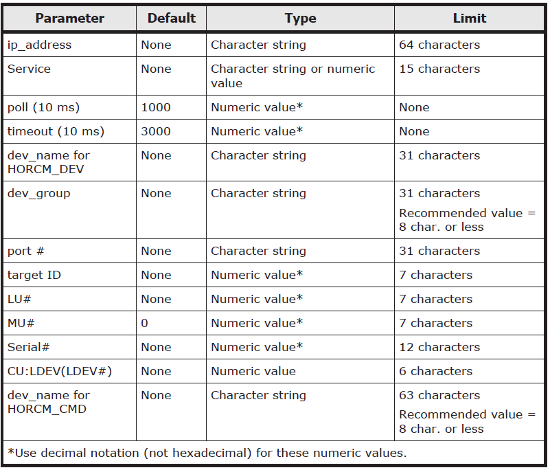
- HORCM_MON – Information for monitoring the HORCM instance. Includes the IP address of the primary server, HORCM instance or service, polling interval for monitoring paired volumes and timeout period for communication with the remote server.
- HORCM_CMD – Command device from the protected storage system. Replace the number with the serial number of the primary storage system
- HORCM_LDEV – #dev_group is the group name for the pairs. dev_name is the pair name (Example uses P_VOL_S_VOL). The serial number is the storage system’s serial number) . CU:LDEV(LDEV#) is the LDEV ID of the P-VOL. MU# is the mirror unit number. use MU#0-2 for ShadowImage, Thin Image and Copy-on-Write Snapshot. You do not need to specify MU# for TC, UR and GAD. If you want to specify MU# for TC, UR, and GAD, use MU#h0 for TC and MU#h0-h3 for UR and GAD.
- HORCM_INST – #dev_group is the group name for the pairs. ip address is the network address of the remote SRM server. service is the remote HORCM instance
Example HORCM1.conf for the secondary site remote replication pair
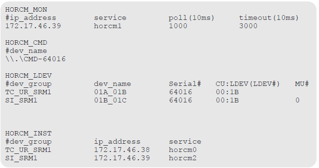
- HORCM_MON – Shows the IP address of the secondary server, HORCM instance or service, polling interval for monitoring paired volumes, and timeout period for communication with the remote server
- HORCM_CMD – Shows the command device on the remote site. Note that the instance or service is increased from the primary instance by 1. Use the storage systems serial number
- HORCM_LDEV – Shows the same group and device name for the pair as used in the primary site HORCM file. the second entry in this section is a group for the ShadowImage pair used for testing. the remote pair’s S-VOL is in the system pair’s P-VOL When using ShadowImage for the in-system pair, make sure that the MU number is set for the P-VOL.
- HORCM_INST – Shows the pair’s group name and the IP address and service number of the primary host. the second entry in the system shows the secondary host address
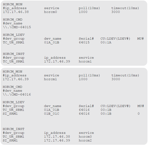
- The TC or UR group must be defined before the SI group.
- The MU# (h0-h3) for UR and GAD devices must be specified.
- The MU# for ShadowImage devices must be specified. If MU#1 or MU#2 are used, the environment variable RMSRATMU must be set
Here are the 2 files together so you can see how it all works
- Do not edit the configuration definition file while CCI is running. Shut
down CCI, edit the configuration file as needed, and then restart CCI.
(horcmshutdowm) When you change the system configuration, it is required to shut down CCI once and rewrite the configuration definition file to match with the change and then restart CCI.
(horcmstart) When you change the storage system configuration (microprogram, cache capacity, LU path, and so on), you must restart CCI regardless of the necessity of the configuration definition file editing. When you restart CCI, confirm that there is no contradiction in the connection configuration by using the “-c” option of the pairdisplay command and the raidqry command. However, you cannot confirm the consistency of the P-VOL and S-VOL capacity with the “-c” option of pairdisplay command. Confirm the capacity of each volume by using the raidcom command - The HORCM.conf file has set parameters as seen below
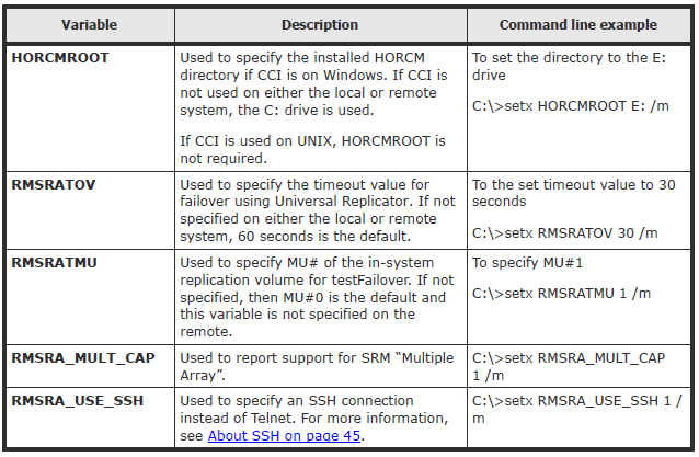
Environment variables
RMSRA20 requires that the following system environment variables be defined in order to make certain parameters available
Sometimes it may be worth speaking to Hitachi about whether these are needed for certain environments as we have none set at the moment in ours but it is here for reference
Install the Hitachi SRA – Hitachi_Raid_Manager_SRA_Ver02.03.01.zip
- Extract the installer from the zip – HITACHI_RMHTCSRA_X64-02-03-01.exe
- Run as Administrator
- Accept the License Agreement
- Choose a destination. I had to change my path to the D Drive as this is where my SRM installation is located
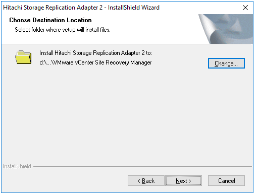
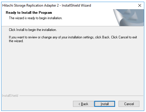
- Click Next and Install
- Restart the VMware Site Recovery Manager Service on the Protected STM Server
- Install the Hitachi SRA software on the Recovery SRM server
- Restart the VMware Site Recovery Manager Service on the Recovery SRM Server
Find the Command Device Name and Array Serial number on each SRM Server
First we need to find the Command Device Name and the serial number of the array on each SRM Server
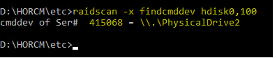
- On the Primary SRM Server, open an elevated command prompt and navigate to the horcm\etc folder on D:
- Run the following command to identify the arrays cmddev name and the serial number
- raidscan -x findcmddev hdisk0,100
- The primary array serial number is 415068
- The command device is \\.\PhysicalDrive2
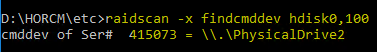
- On the Secondary SRM Server, open an elevated command prompt and navigate to the horcm\etc folder on D:
- Run the following command to identify the arrays cmddev name and the serial number
- raidscan -x findcmddev hdisk0,100
- The primary array serial number is 415073
- The command device is \\.\PhysicalDrive2
Add the details above to the HORCM100.conf on the Primary SRM Server and HORCM101.conf file on the Secondary SRM Server
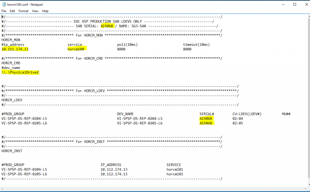
- At the top of the HORCM100.conf file we put in the serial number of the array as it makes it easier for us to liaise with Support and Storage if we have an issue, but it is not mandatory
- In HORCM_MON we add the IP address of the Primary SRM server and the serial number of the Primary storage array
- In HORCM_CMD, we put in the command device which is \\.\PhysicalDrive2
- Note: A lot of info is already there but I will talk through these as we go.
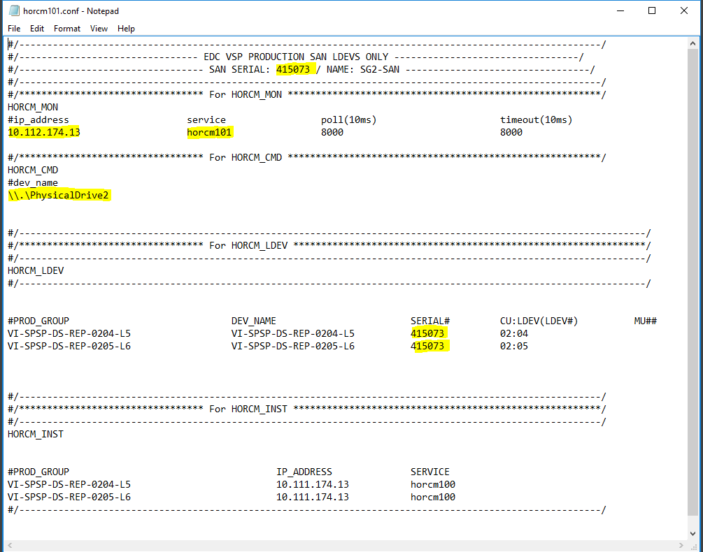
- At the top of the HORCM101.conf file we put in the serial number of the array as it makes it easier for us to liaise with Support and Storage if we have an issue, but it is not mandatory
- In HORCM_MON we add the IP address of the Secondary SRM server and the serial number of the Primary storage array
- In HORCM_CMD, we put in the command device which is \\.\PhysicalDrive2
Configure the opposite details for each site within the HORCM100.conf file on the Primary SRM server and the HORCM101.conf file on the Secondary SRM Server
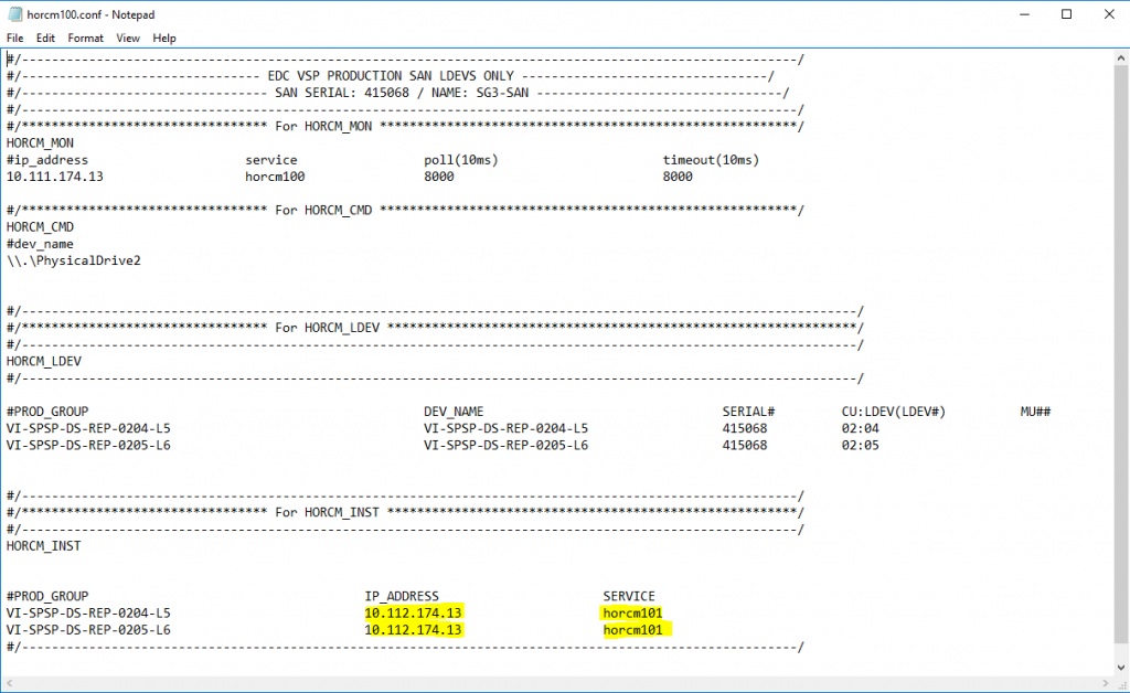
- Under the section HORCM_INST within the HORCM100.conf file, fill in the below details highlighted in yellow
- Put in the IP address of the Secondary SRM server
- Put in the name of the HORCM101.conf file on the Secondary SRM server
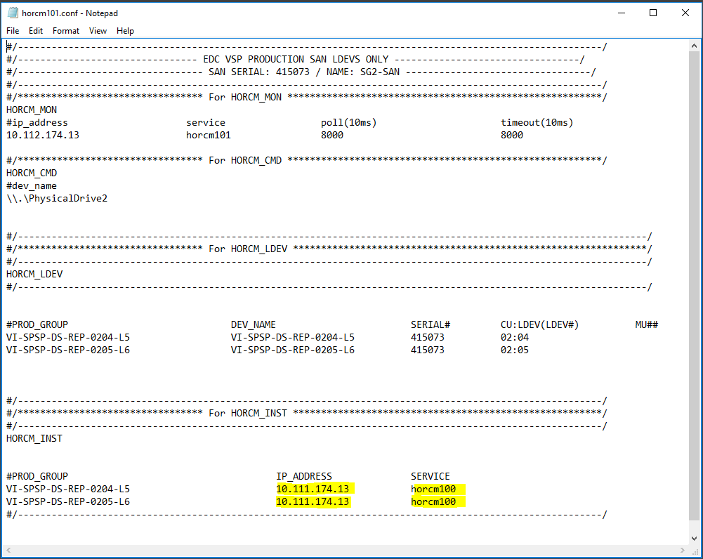
- Under the section HORCM_INST within the HORCM101.conf file, fill in the below details highlighted in yellow
- Put in the IP address of the Primary SRM server
- Put in the name of the HORCM100.conf file on the Primary SRM server
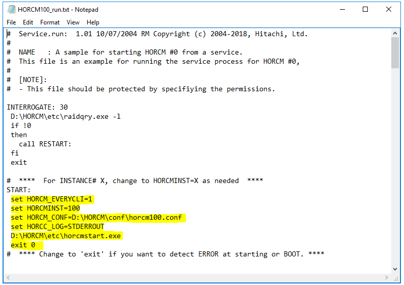
Configure the HORCM100_run.txt on the Primary SRM Server and then HORCM101_run.txt file on the Secondary SRM Server
- Navigate to D:\HORCM\Tool\HORCM100_run.txt
- Set the below parameters highlighted in yellow below
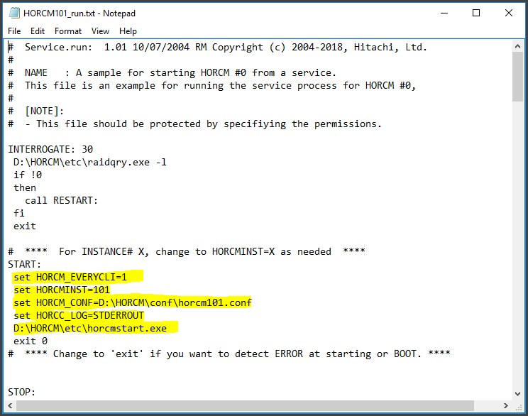
- Navigate to D:\HORCM\Tool\HORCM101_run.txt
- Set the below parameters highlighted in yellow below
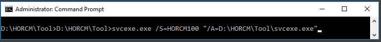
Run the following command from the tool folder on the Primary SRM Server and Secondary SRM Server
- Run the following command from the tool folder on the Primary SRM Server and change the HORCM number to the one you are using
- D:\HORCM\Tool>svcexe.exe /S=HORCM100 “/A=D:\HORCM\Tool\svcexe.exe”
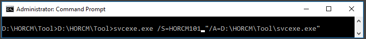
- Run the following command from the tool folder on the Secondary SRM Server and change the HORCM number to the one you are using
- D:\HORCM\Tool>svcexe.exe /S=HORCM101 “/A=D:\HORCM\Tool\svcexe.exe
Add an Inbound Windows Firewall rule for Port 11088 on the Primary SRM Server and an Inbound Windows Firewall rule on the Secondary SRM Server
- Go to Windows Firewall with Advanced Security
- On Inbound rules, select new Rule
- On Rule Type, select Port
- Select UDP
- Put in 11088
- Select Allow the Connection
- Untick Public
- Put in a name HORCM100 In

- Go to Windows Firewall with Advanced Security
- On Inbound rules, select new Rule
- On Rule Type, select Port
- Select UDP
- Put in 11089
- Select Allow the Connection
- Untick Public
- Put in a name HORCM101 In

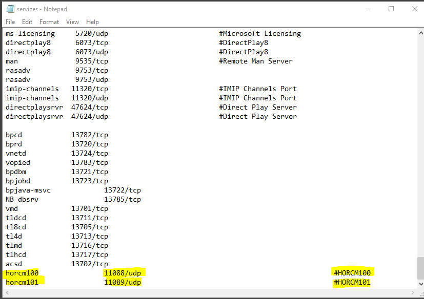
Update the Services file and start the service on the Primary SRM Server and the Secondary SRM Server
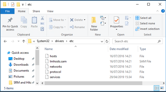
- On the Primary Server, go to C:\Windows\System32\drivers\etc
- Update the services file under c:\windows\system32\drivers\etc\services
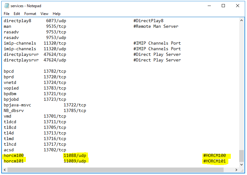
- Repeat the above on the Secondary SRM Server
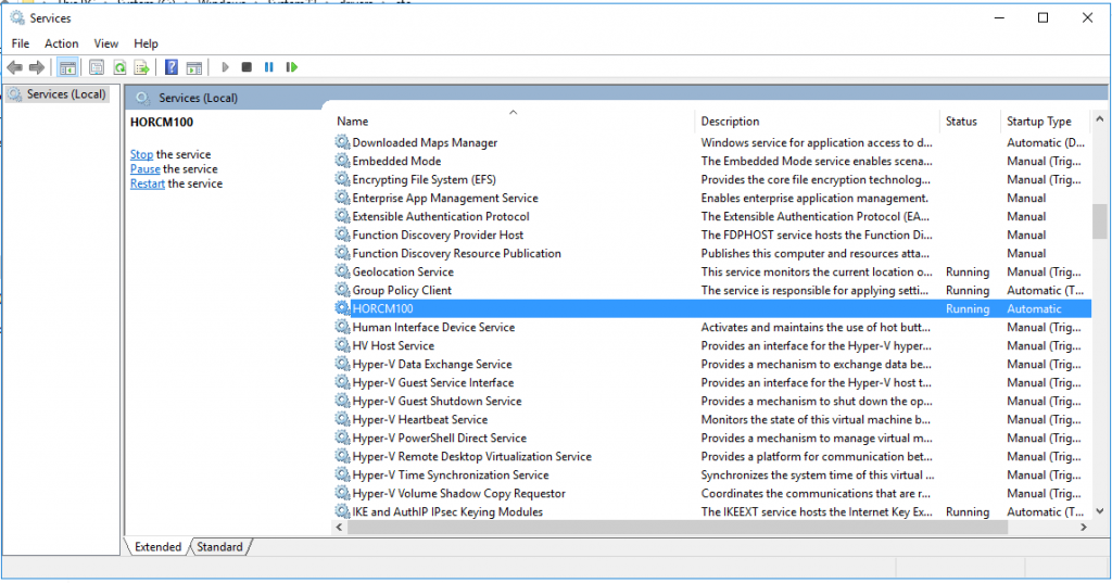
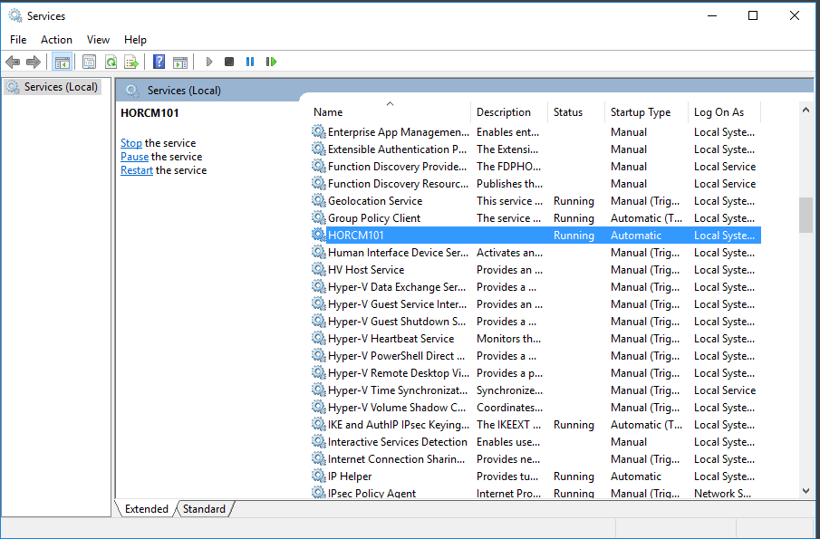
Start the HORCM100 Service on the Primary SRM Server and start the HORCM101 service on the Secondary SRM Server
- On the Primary SRM Server, click Start – Run – services.msc
- Start HORCM100
- On the Secondary SRM Server, click Start – Run – services.msc
- Start HORCM101
Next we need to speak to the Storage Team and obtain our replicated LUNs then pair them
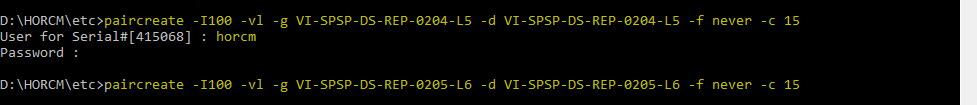
Note: You will be prompted for a username and password – Ask your storage admin to create one. Ours is called HORCM in the command below.
paircreate -I100 -vl -g VI-SPSP-DS-REP-0204-L5 -d VI-SPSP-DS-REP-0204-L5 -f never -c 15
paircreate -I100 -vl -g VI-SPSP-DS-REP-0205-L6 -d VI-SPSP-DS-REP-0205-L6 -f never -c 15
There is a very important note to add here, the –vl flag in the below commands tells the SAN to create the pairing based on the local HORCM instance that is referenced (100 in the case of the commands, as indicated by the –IH100 flag). What this means is that the local LDEV will become the Primary replication LDEV, with the LDEV in the other datacentre becoming the Secondary. So in this case because we have run the command from the PDC SRM server the replication will go from PDC > SDC, so the datastore in vCenter has to be created in PDC and will be replicated to SDC. With this in mind, it is vital that the pair creation commands are run from the correct SRM server, if the datastores are to be created in PDC then the pairs need to be created on the PDC SRM server. Otherwise the replication will be the wrong way around. After the pair create commands have been run, you can rerun the pair display commands to confirm the correct Primary and Secondary sites, this is discussed in more detail below.
Next Run a Pair display to make sure the LUNs are paired
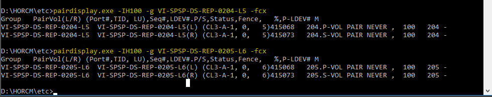
The –g flag dictates which group will be checked (same as DEV_GROUP from HORCM file).
The –IH flag dictates which HORCM instance to query. The –fxc flags dictate which info will be shown be the command.
The –fxc flags dictate which info will be shown be the command.
Next steps – Log into vCenter and Site Recovery Manager
You will be on the Site pair page. You can also see the other 3 options
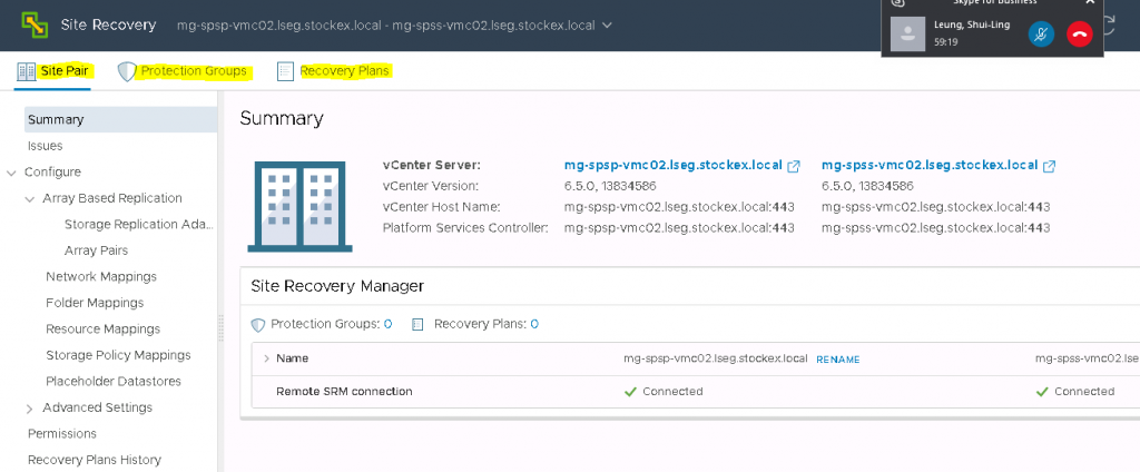
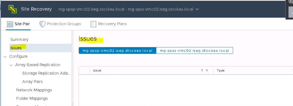
Click the issues to see if there are any problems
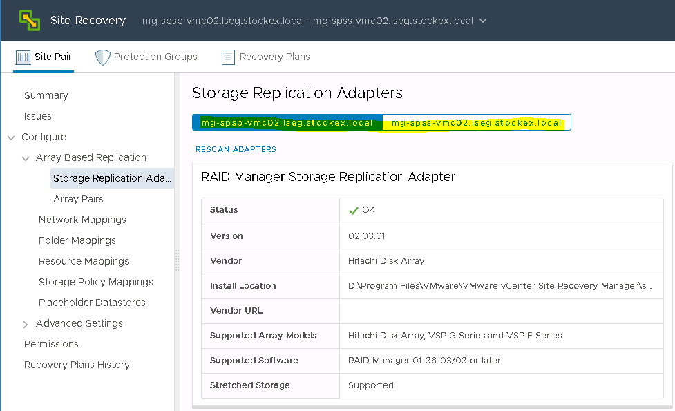
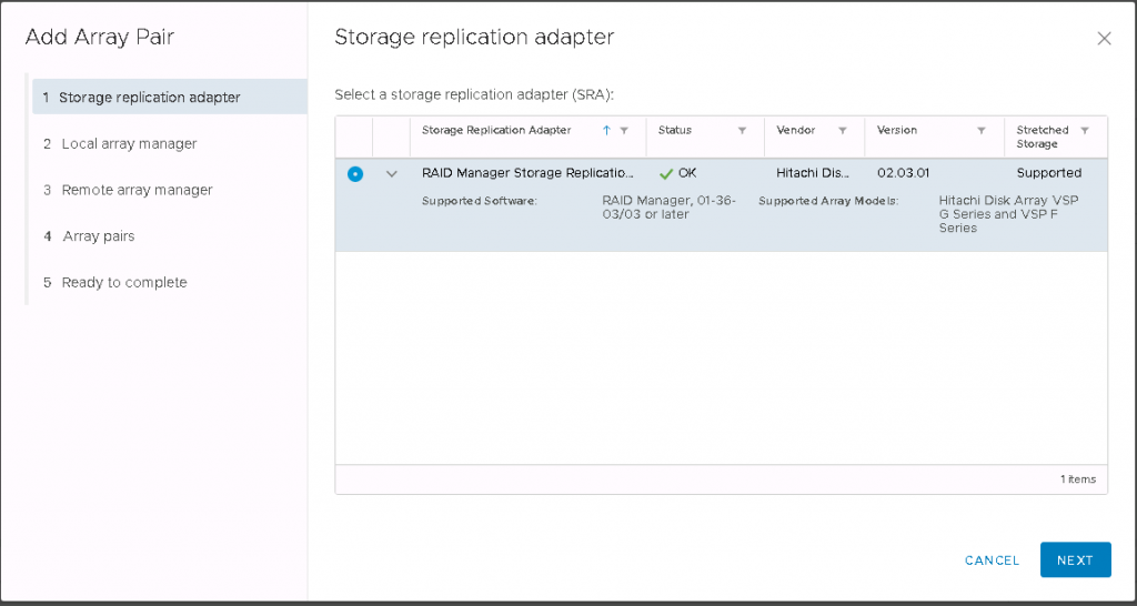
Next go to Array Based Replication and click on Storage Replication Adapters. Clcik both sites to make sure everything is ok
Click on Array Pairs and click Add
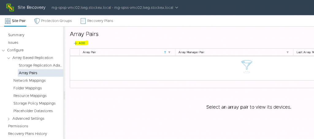
The Array pair wizard will open
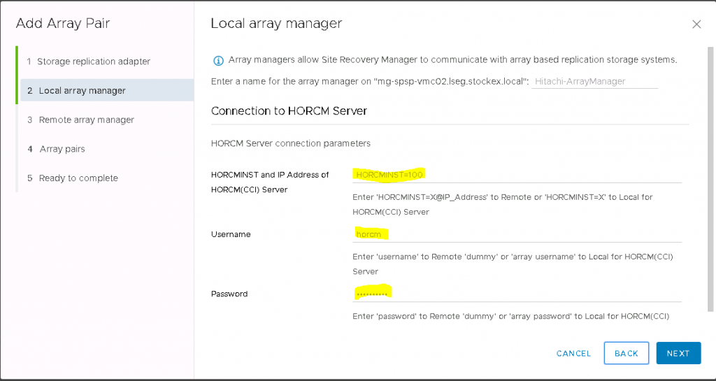
For the name, enter Hitachi-ArrayManager
For the local protected HORCM site, enter HORCMINST=100 (100 is our HORCM instance on our protected site)
For the username and password, enter the credentials you have been given by your storage administrator.
In our case the username is horcm and then put in the password
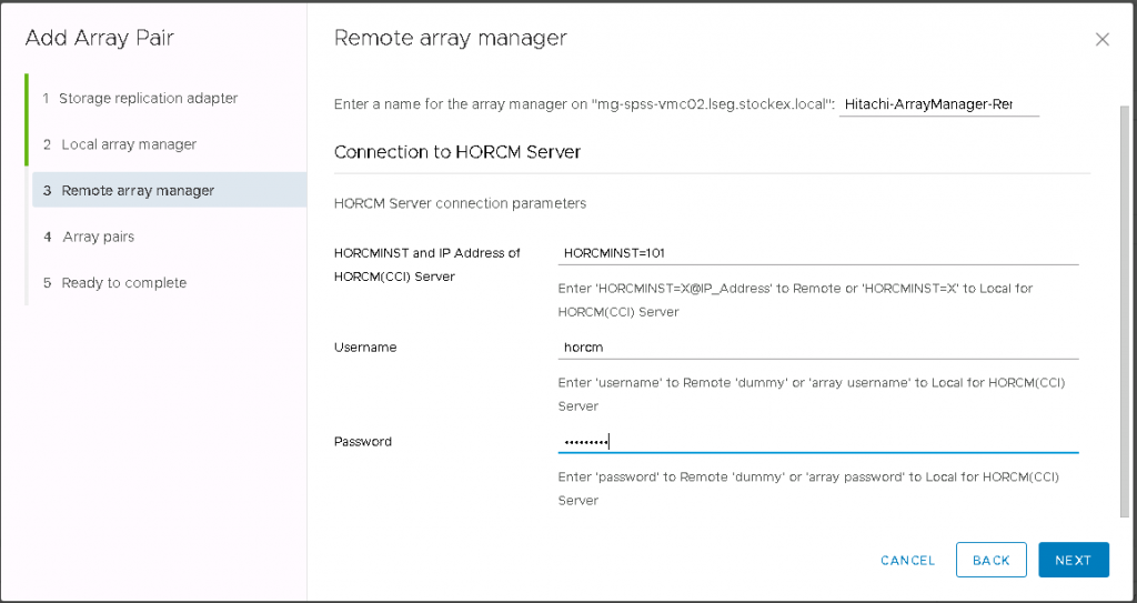
For the remote recovery HORCM site, enter Hitachi-ArrayManager-Remote
For the remote recovery HORCM site, enter HORCMINST=101 (101 is our HORCM instance on our recovery site)
For the username and password, enter the credentials you have been given by your storage administrator.
In our case the username is horcm and then put in the password
The array pairs screen will then come up
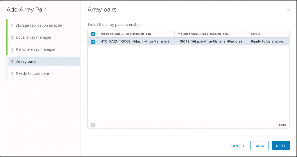
Click Next and check the last screen and finish
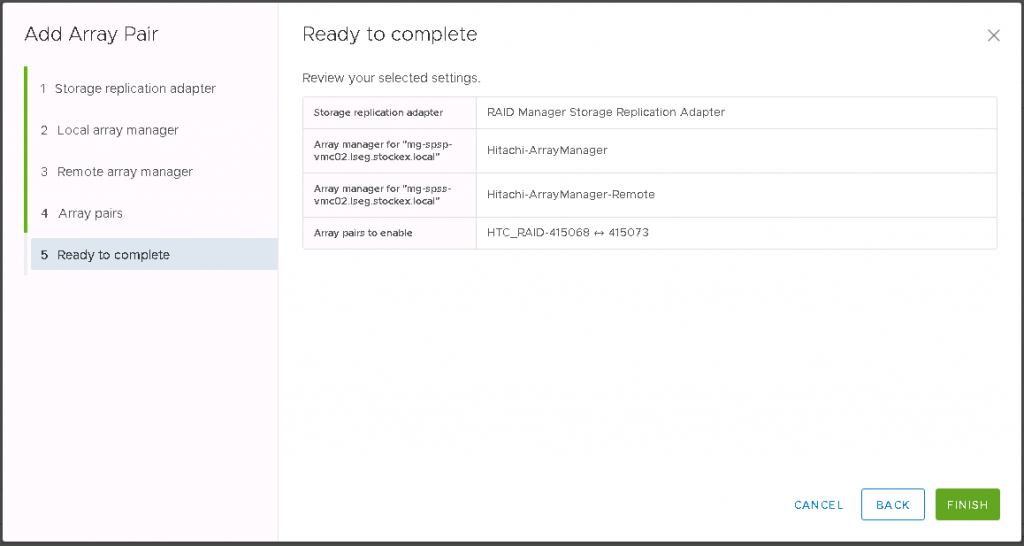
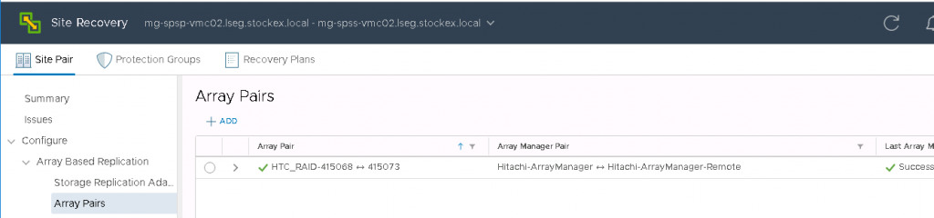
You will now see the paired arrays
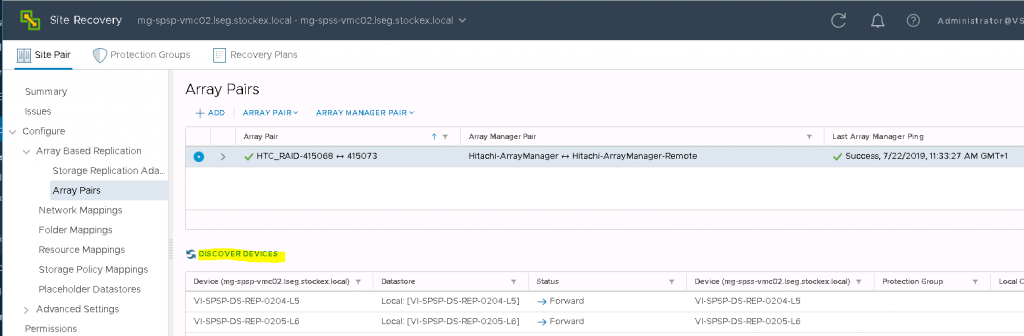
If you click on the Array pair, then below you will see the paired datastores
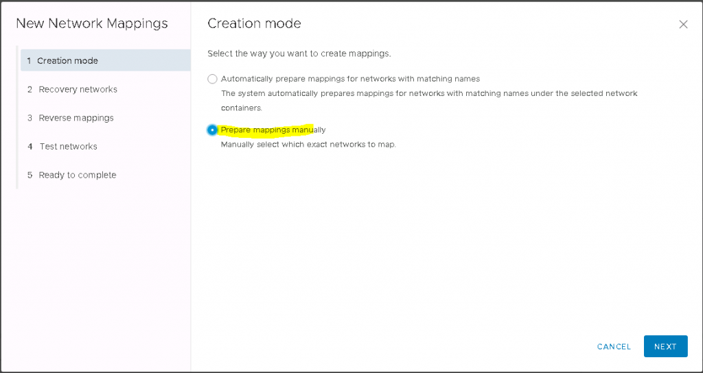
Next we will configure Network Mappings
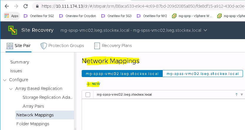
Select the Recovery network
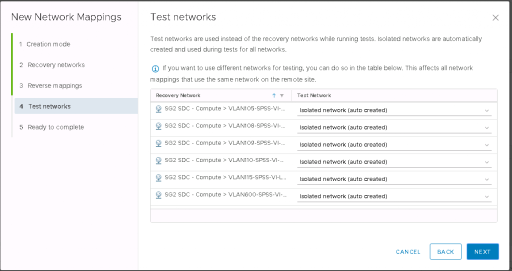
Check the Test networks. These are used instead of the recovery networks while running tests
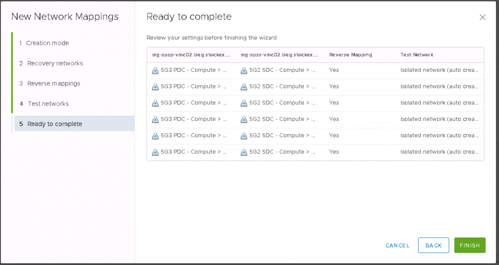
Check the Ready to Complete page and click Finish
Next, we will go through Folder Mappings
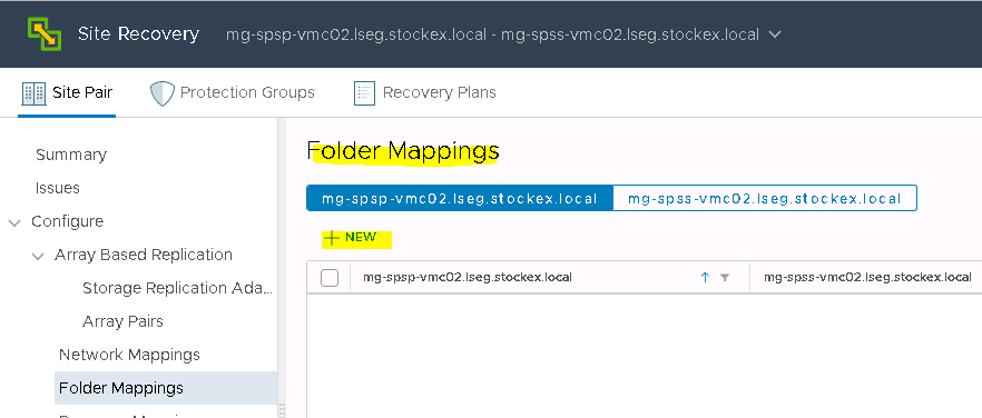
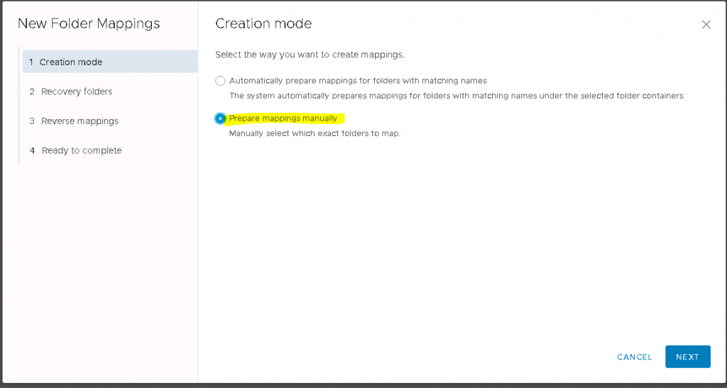
Choose Prepare Mappings manually
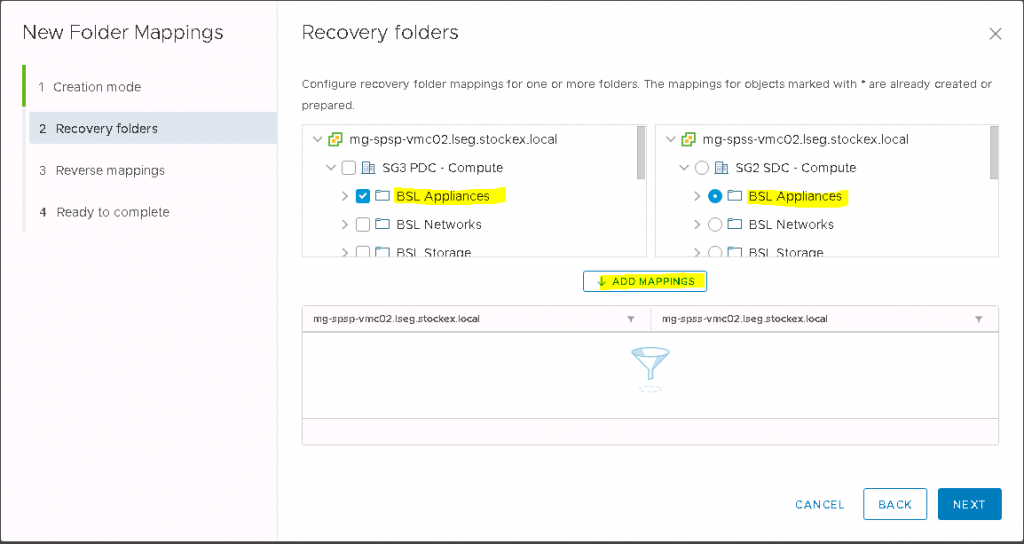
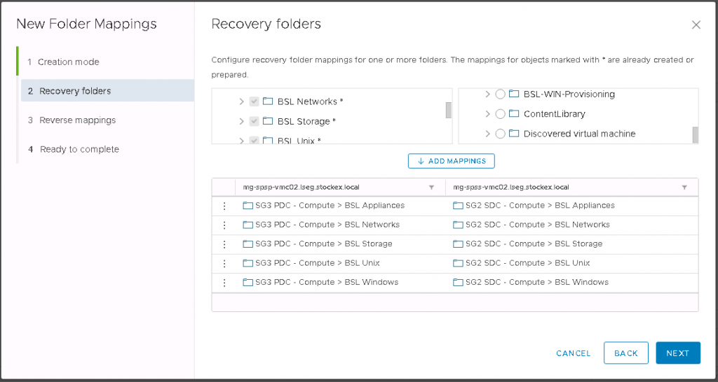
Select the mappings on both sides and click Add
The mappings will look similar to the below screen-print
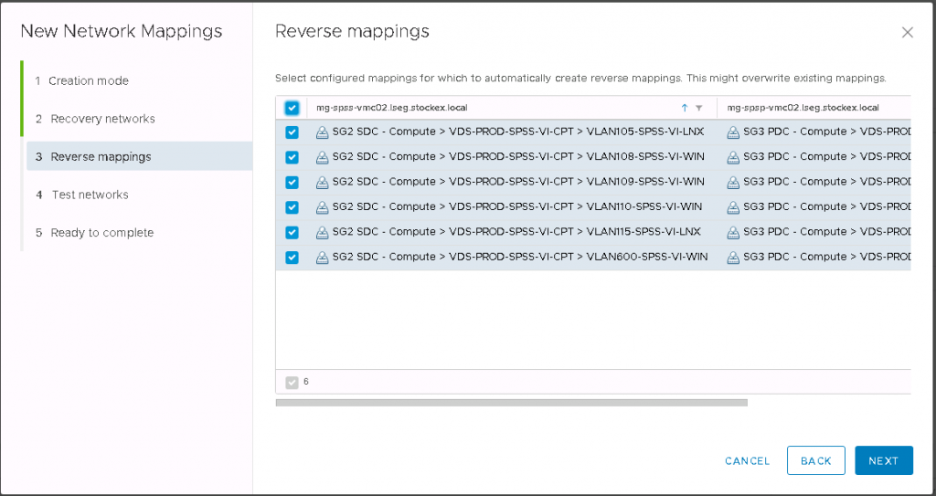
Select the Reverse mappings
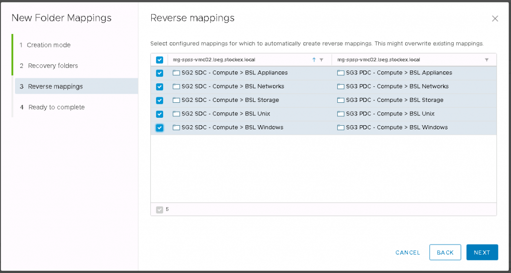
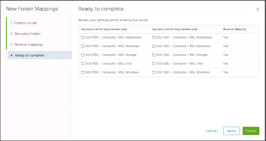
Click Finish after checking the Final screen
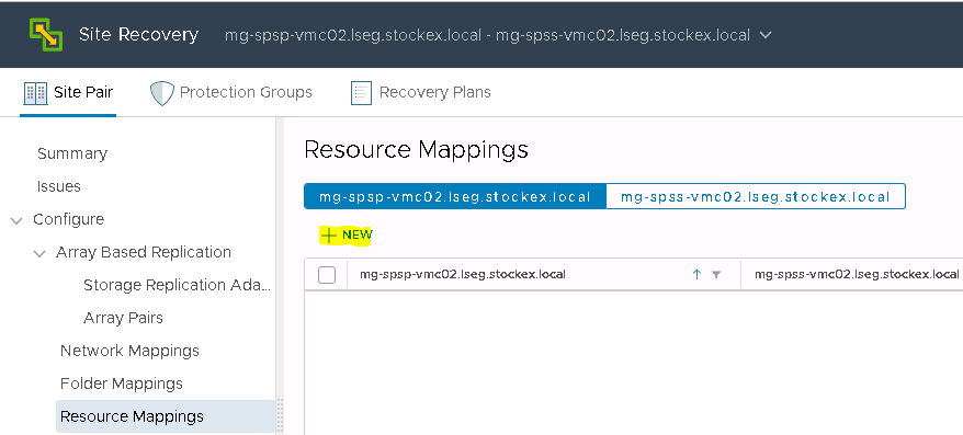
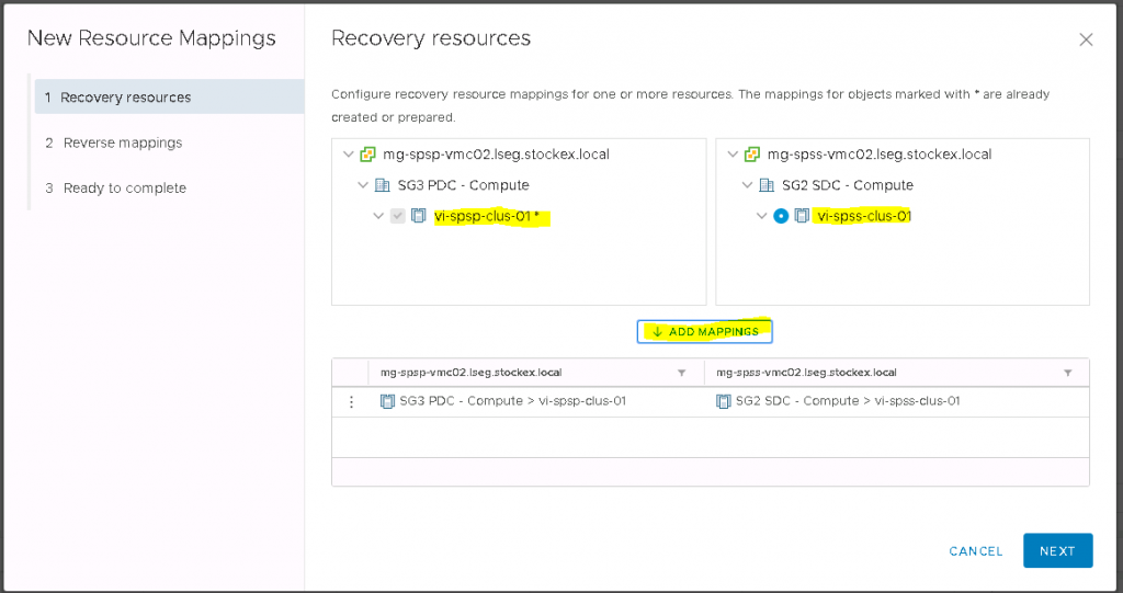
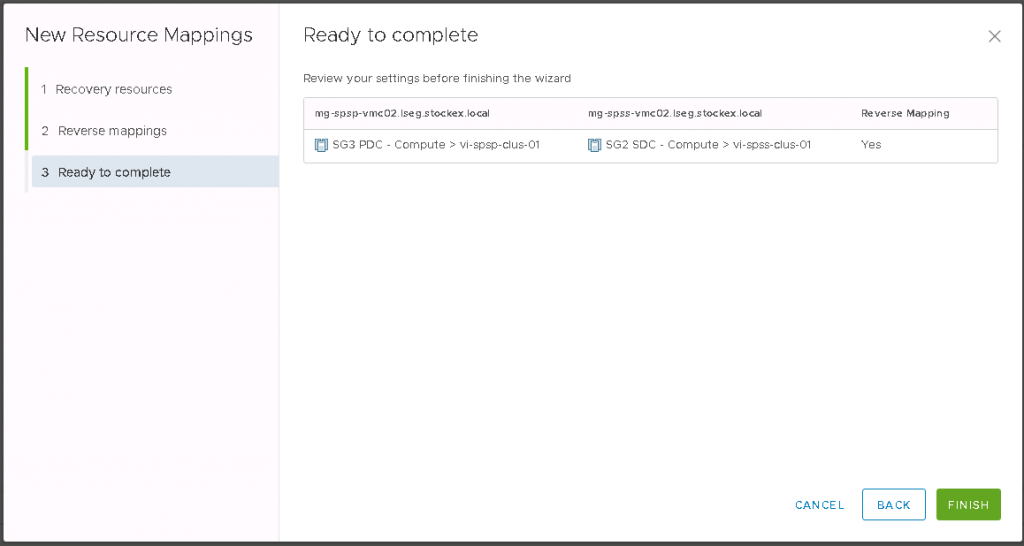
Next go to Resource Mapping
Select the Cluster Resource
Select the Reverse mappings
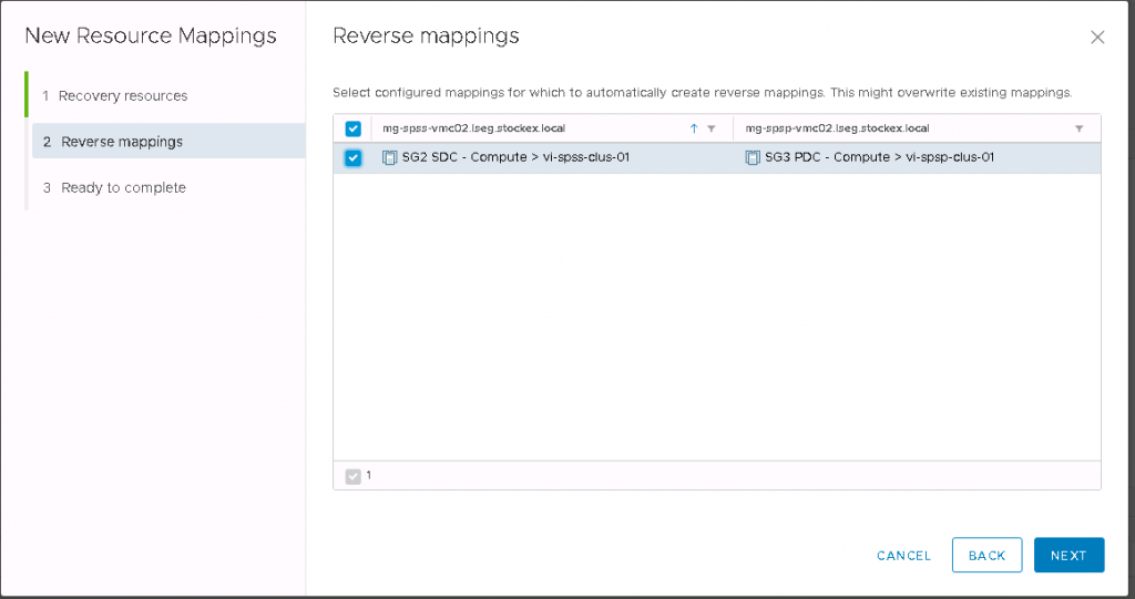
Check the Final Page and click finish
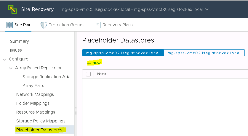
Placeholder Datastores
When you create an array-based replication protection group that contains datastore groups or a vSphere Replication protection group that contains individual virtual machines, Site Recovery Manager creates a placeholder virtual machine at the recovery site for each of the virtual machines in the protection group.
A placeholder virtual machine is a subset of virtual machine files. Site Recovery Manager uses that subset of files to register a virtual machine with vCenter Server on the recovery site.
The files of the placeholder virtual machines are very small, and do not represent full copies of the protected virtual machines. The placeholder virtual machine does not have any disks attached to it. The placeholder virtual machine reserves compute resources on the recovery site, and provides the location in the vCenter Server inventory to which the protected virtual machine recovers when you run recovery.
The presence of placeholder virtual machines on the recovery site inventory provides a visual indication to vCenter Server administrators that the virtual machines are protected by Site Recovery Manager. The placeholders also indicate to vCenter Server administrators that the virtual machines can power on and start consuming local resources when Site Recovery Manager runs tests or runs a recovery plan.
When you recover a protected virtual machine by testing or running a recovery plan, Site Recovery Manager replaces the placeholder with the recovered virtual machine and powers it on according to the settings of the recovery plan. After a recovery plan test finishes, Site Recovery Manager restores the placeholders and powers off the recovered virtual machines as part of the cleanup process.
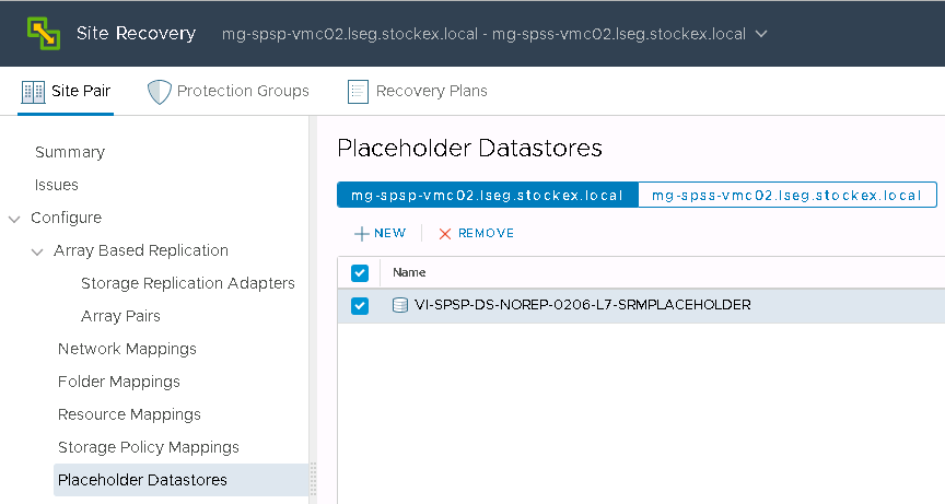
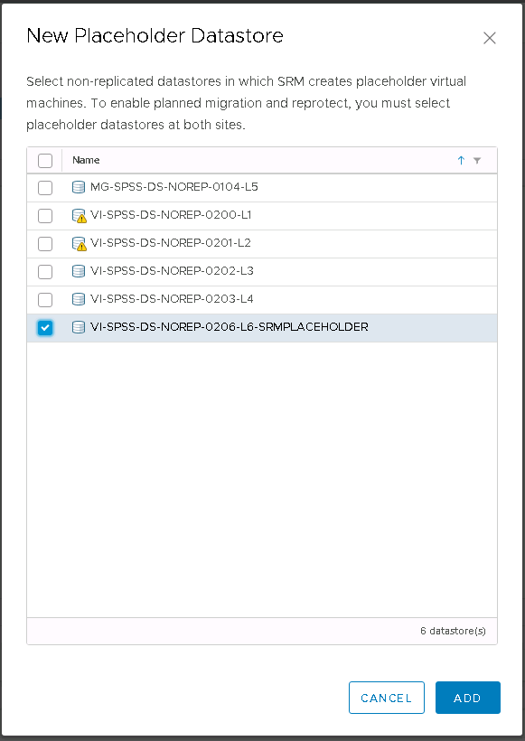
Go to Site Recovery Manager > Configure > Placeholder Datastores and click +New
Choose the datastore you created to be the Placeholder Datastore
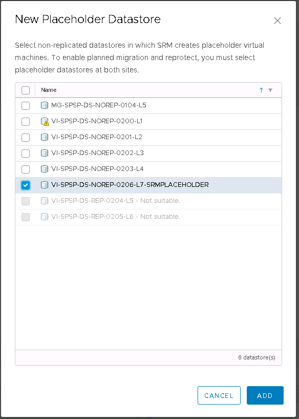
You will then see the Placeholder Datastore added in SRM
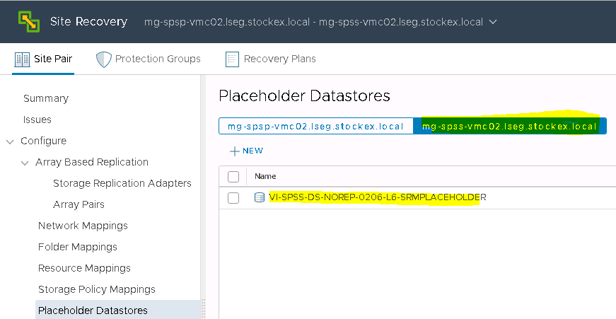
Select the Placeholder Datastore
You will now see your Recovery Placeholder Datastore under the Recovery vCenter
Next we need to create a Protection Group
In SRM, protection groups are a way of grouping VMs that will be recovered together. A protection group contains VMs whose data has been replicated by either array-based replication (ABR) or vSphere replication (VR). A protection group cannot contain VMs replicated by more than one replication solution (eg. same VM protected by both vSphere replication and array-based replication) and, a VM can only belong to a single protection group.
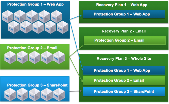
How do Protection Groups fit into SRM?
Recovery Plans in SRM are like an automated run book, controlling all the steps in the recovery process. The recovery plan is the level at which actions like Failover, Planned Migration, Testing and Reprotect are conducted. A recovery plan contains one or more protection groups and a protection group can be included in more than one recovery plan. This provides for the flexibility to test or recover the email application by itself and also test or recover a group of applications or the entire site. Thanks to Kato Grace for this information and diagram below
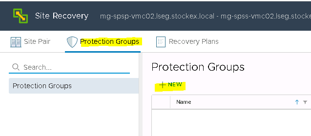
Click New in the Protection Group screen
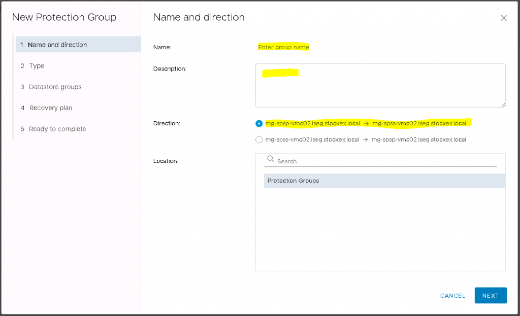
Fill in the necessary details and make sure you select the right direction
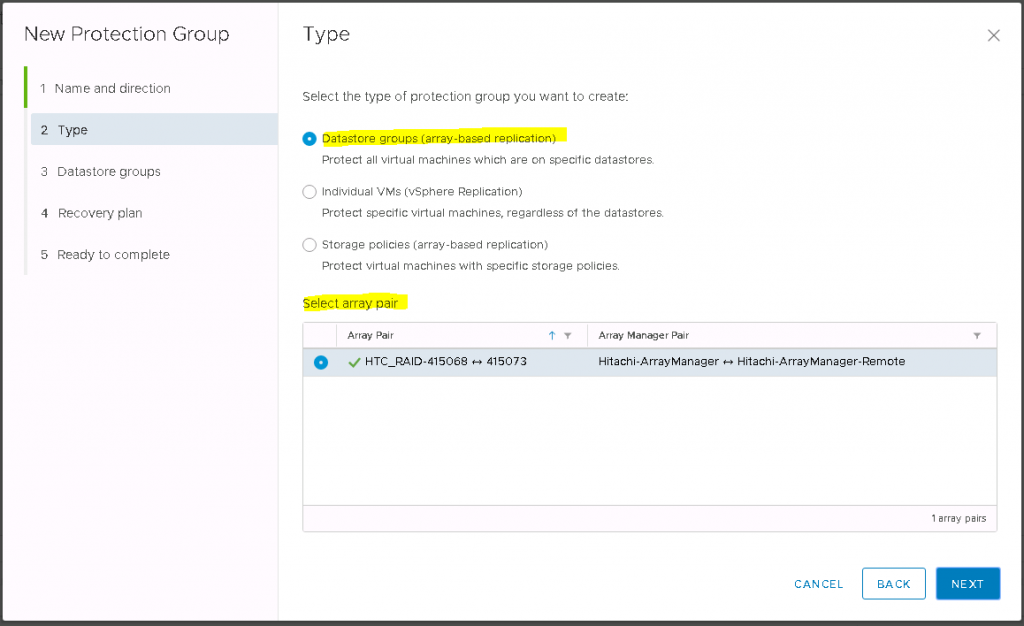
Select the type of replication (In this case we are using Datastore groups (array-based replication)
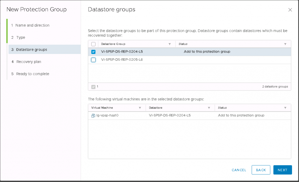
Click Next and choose the Datastore(s) you want to add to the Protection Group
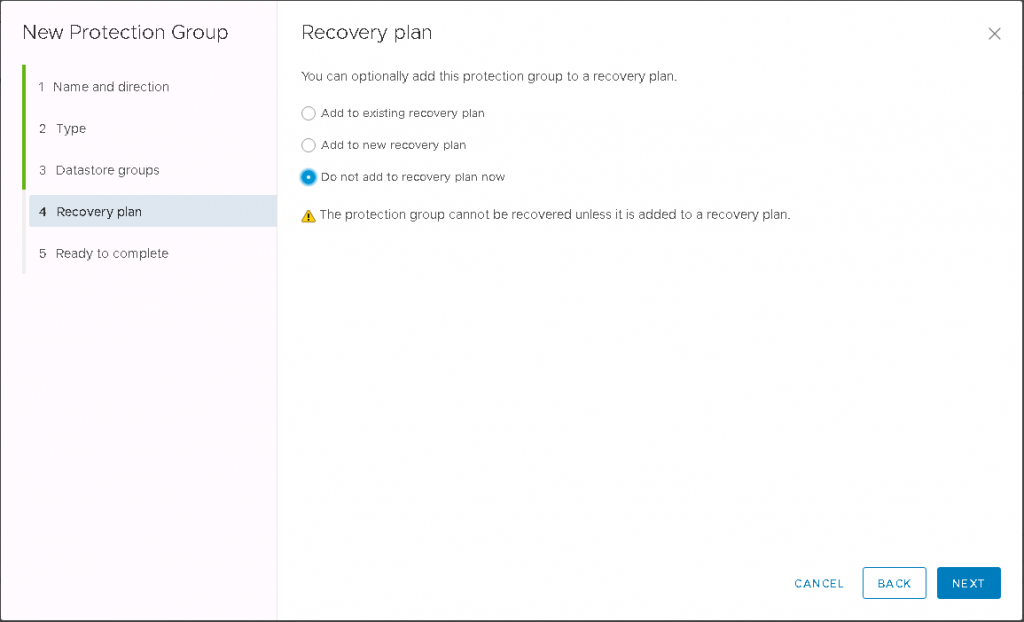
Select whether you want to add the Protection Group to a Recovery Plan. For now I will say Do not add as we will go through a Recovery Plan next
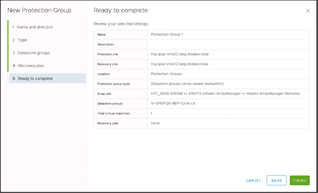
Check the Ready to Complete screen and make sure everything is as expected. Click Finish.
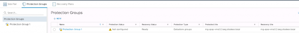
You will then be back to the Protection Group page which looks like the following
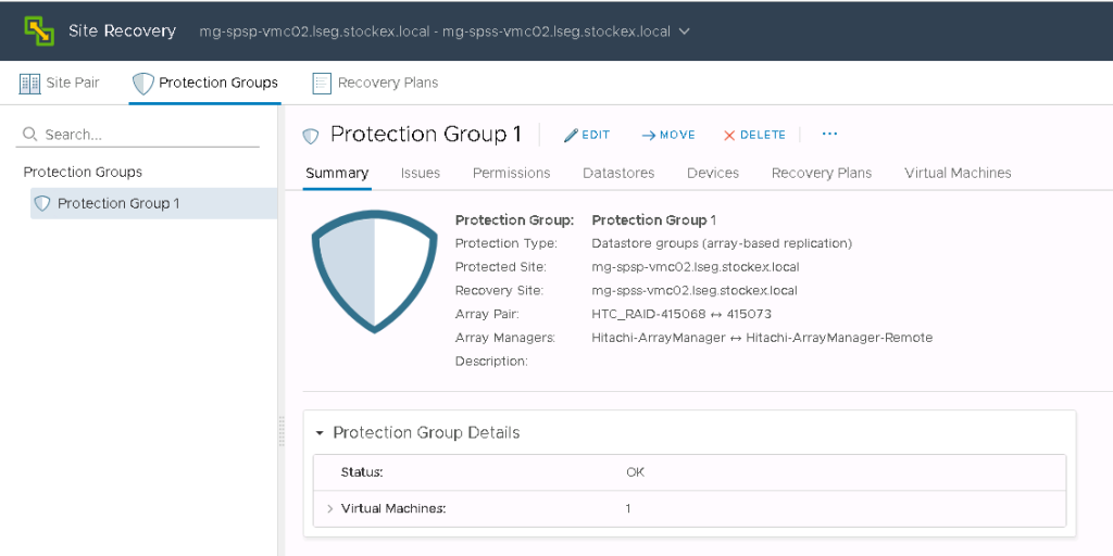
If you click on the Protection Group, you will see all the details. Check any issues and have a look through the tabs to check everything looks as expected.
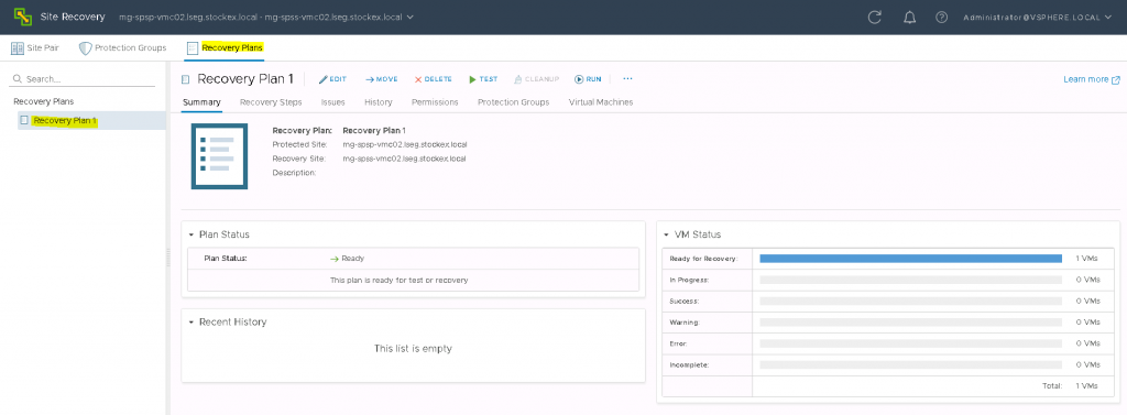
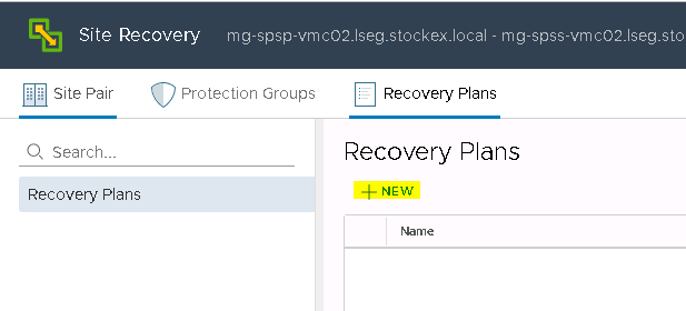
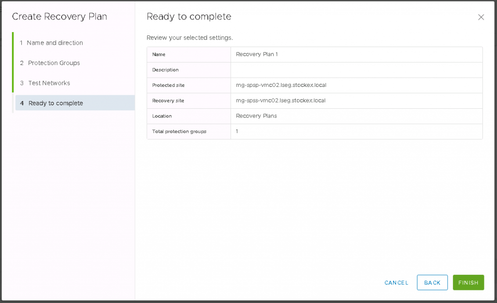
Next we will set up a Recovery Plan. Click on the Recovery Plan tab and click New
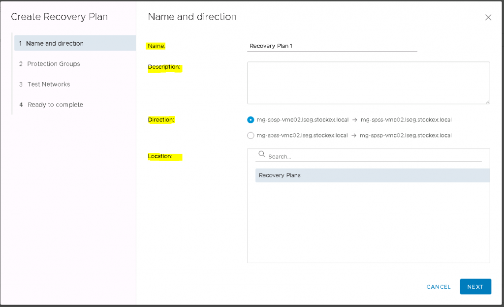
Put in a Name, Description, Direction and Location
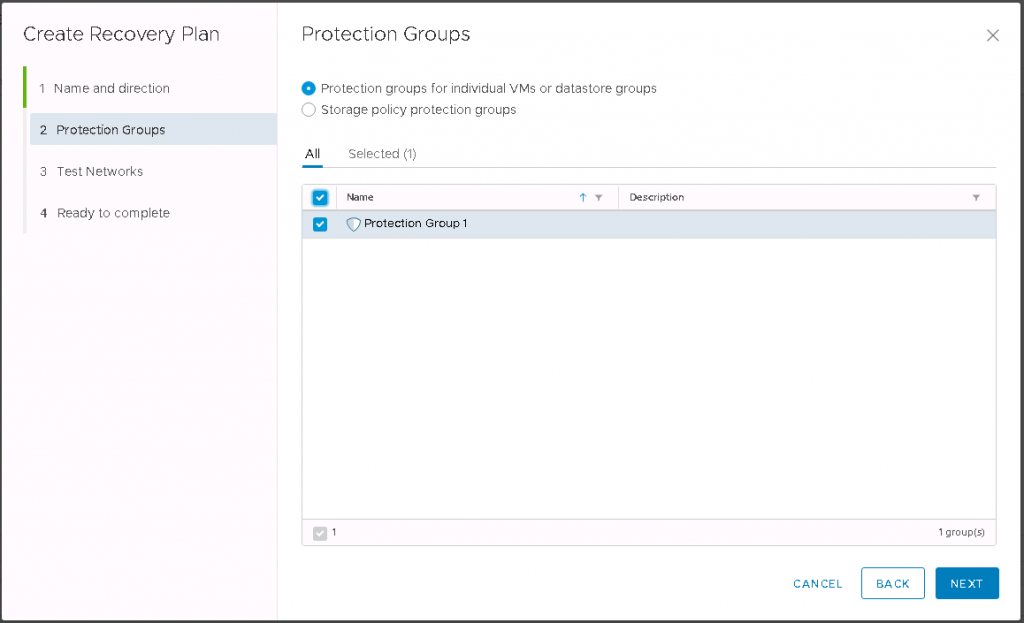
Choose your Protection Group(s)
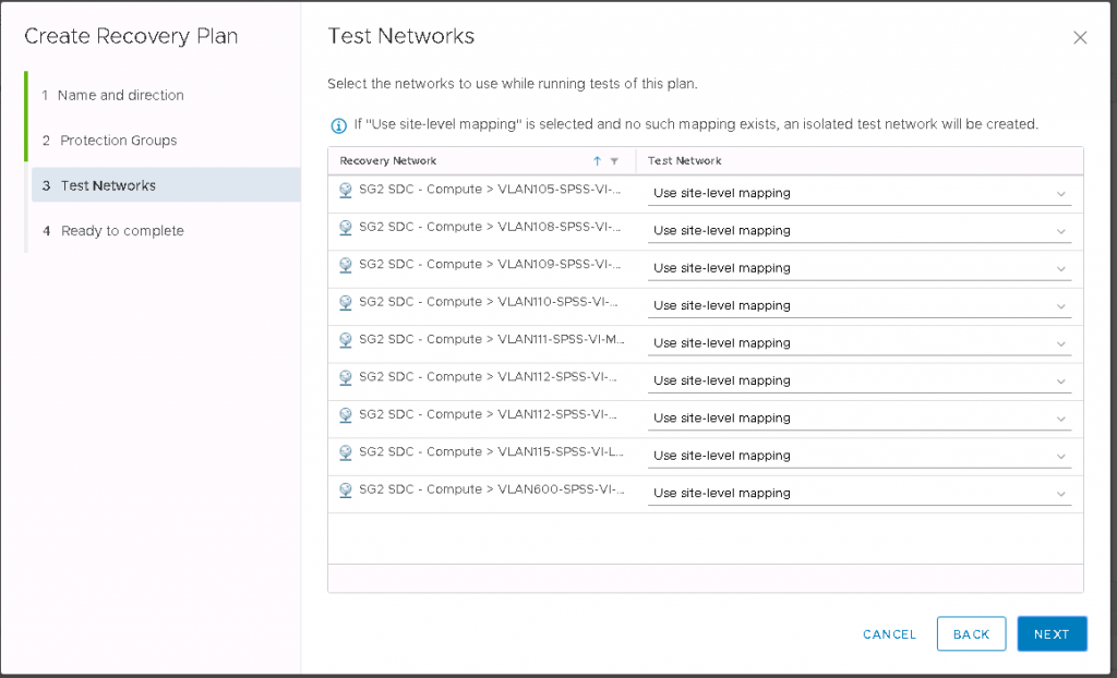
Leave everything as it is in the Test networks Screen
Click Next and on the Ready to Complete screen, check the details and click Finish
Click on the Recovery Plan tab and then on your previously created Recovery Plan