What is Network Teaming and Load Balancing?
Network Teaming is the process of combining NICs to provide bandwidth and failover to a switch. Load balancing and failover policies allow you to determine how network traffic is distributed between network adapters and how to re-route traffic in the event of adapter failure.
You can set NIC Teaming on the following objects
- Standard Switch
- Distributed Switch
- Standard Port Group
- Distributed Port Group
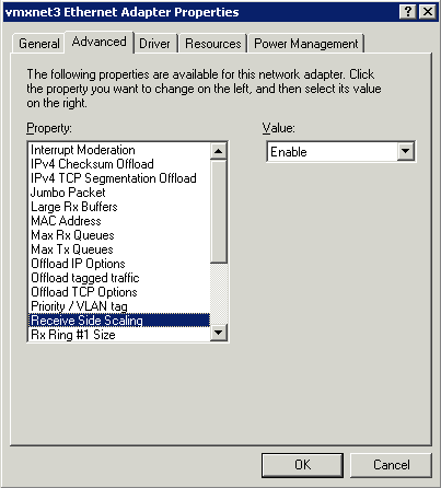
Settings Overview for a Standard Switch
Procedure for a Standard Switch and a Standard Port Group
- Log in to the vSphere Client and select the server from the inventory panel.
The hardware configuration page for this server appears. - Click the Configuration tab and click Networking.
- Select a Standard Switch or Standard Port Group and click Edit.
- Click the Ports tab.
- To edit the Failover and Load Balancing values, select the standard switch item and click Properties.
- Click the NIC Teaming tab
- You can override the failover order at the port group level. By default, new adapters are active for all policies. New adapters carry traffic for the standard switch and its port group unless you specify otherwise.
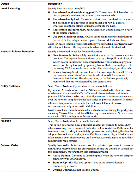
Specify how to choose an uplink.
- Route based on the originating virtual port
- Choose an uplink based on the virtual port where the traffic entered the distributed switch. This is the default configuration and the one most commonly deployed.
- When you use this setting, traffic from a given virtual Ethernet adapter is consistently sent to the same physical adapter unless there is a failover to another adapter in the NIC team.
- Replies are received on the same physical adapter as the physical switch learns the port association.
- This setting provides an even distribution of traffic if the number of virtual Ethernet adapters is greater than the number of physical adapters.
- A given virtual machine cannot use more than one physical Ethernet adapter at any given time unless it has multiple virtual adapters.
- This setting places slightly less load on the ESX Server host than the MAC hash setting.
- Route based on ip hash
- Choose an uplink based on a hash of the source and destination IP addresses of each packet. For non-IP packets, whatever is at those offsets is used to compute the hash.
- Evenness of traffic distribution depends on the number of TCP/IP sessions to unique destinations. There is no benefit for bulk transfer between a single pair of hosts.
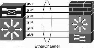
- You can use link aggregation — grouping multiple physical adapters to create a fast network pipe for a single virtual adapter in a virtual machine.
- When you configure the system to use link aggregation, packet reflections are prevented because aggregated ports do not retransmit broadcast or multicast traffic.
- The physical switch sees the client MAC address on multiple ports. There is no way to predict which physical Ethernet adapter will receive inbound traffic.
- All adapters in the NIC team must be attached to the same physical switch or an appropriate set of stacked physical switches. (Contact your switch vendor to find out whether 802.3ad teaming is supported across multiple stacked chassis.) That switch or set of stacked switches must be 802.3ad-compliant and configured to use that link-aggregation standard in static mode (that is, with no LACP).
- All adapters must be active. You should make the setting on the virtual switch and ensure that it is inherited by all port groups within that virtual switch
- Route based on source MAC hash
- Choose an uplink based on a hash of the source Ethernet MAC Address
- When you use this setting, traffic from a given virtual Ethernet adapter is consistently sent to the same physical adapter unless there is a failover to another adapter in the NIC team.
- Replies are received on the same physical adapter as the physical switch learns the port association.
- This setting provides an even distribution of traffic if the number of virtual Ethernet adapters is greater than the number of physical adapters.
- A given virtual machine cannot use more than one physical Ethernet adapter at any given time unless it uses multiple source MAC addresses for traffic it sends.
- Use explicit failover order
Always use the highest order uplink from the list of Active adapters which passes failover detection criteria.
NOTE IP-based Hash teaming requires that the physical switch be configured with etherchannel. For all other options, etherchannel should be disabled.
Settings Overview for a Distributed Switch
Procedure for a Distributed Switch and a Distributed Port Group
- Log in to the vSphere Client and select the server from the inventory panel. The hardware configuration page for this server appears.
- Click the Configuration tab and click Networking.
- Select a Distributed Switch or Distributed Port Group and click Edit.
- Click the Ports tab.
- To edit the Failover and Load Balancing values, select the standard switch item and click Properties.
- Click the NIC Teaming tab
- You can override the failover order at the port group level. By default, new adapters are active for all policies. New adapters carry traffic for the standard switch and its port group unless you specify otherwise.
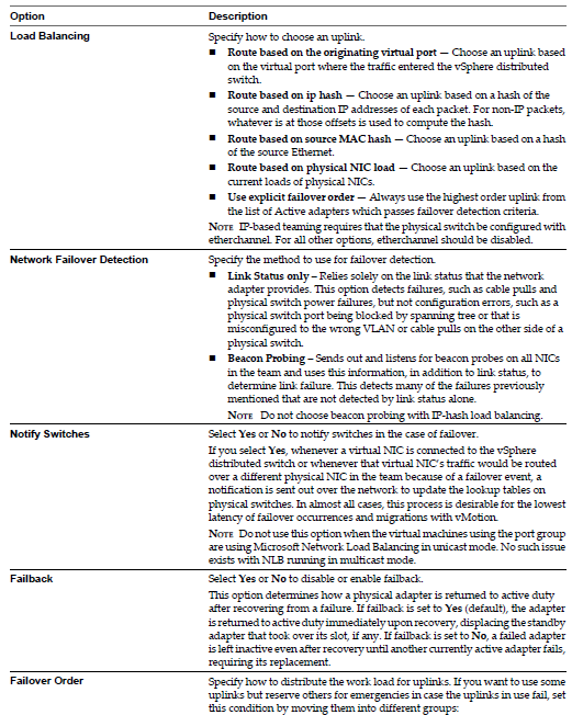
Specify how to choose an uplink.
- Route based on the originating virtual port
- Choose an uplink based on the virtual port where the traffic entered the distributed switch. This is the default configuration and the one most commonly deployed.
- When you use this setting, traffic from a given virtual Ethernet adapter is consistently sent to the same physical adapter unless there is a failover to another adapter in the NIC team.
- Replies are received on the same physical adapter as the physical switch learns the port association.
- This setting provides an even distribution of traffic if the number of virtual Ethernet adapters is greater than the number of physical adapters.
- A given virtual machine cannot use more than one physical Ethernet adapter at any given time unless it has multiple virtual adapters.
- This setting places slightly less load on the ESX Server host than the MAC hash setting.
- Route based on ip hash
- Choose an uplink based on a hash of the source and destination IP addresses of each packet. For non-IP packets, whatever is at those offsets is used to compute the hash.
- Evenness of traffic distribution depends on the number of TCP/IP sessions to unique destinations. There is no benefit for bulk transfer between a single pair of hosts.
- You can use link aggregation — grouping multiple physical adapters to create a fast network pipe for a single virtual adapter in a virtual machine.
- When you configure the system to use link aggregation, packet reflections are prevented because aggregated ports do not retransmit broadcast or multicast traffic.
- The physical switch sees the client MAC address on multiple ports. There is no way to predict which physical Ethernet adapter will receive inbound traffic.
- All adapters in the NIC team must be attached to the same physical switch or an appropriate set of stacked physical switches. (Contact your switch vendor to find out whether 802.3ad teaming is supported across multiple stacked chassis.) That switch or set of stacked switches must be 802.3ad-compliant and configured to use that link-aggregation standard in static mode (that is, with no LACP).
- All adapters must be active. You should make the setting on the virtual switch and ensure that it is inherited by all port groups within that virtual switch
- Route based on source MAC hash
- Choose an uplink based on a hash of the source Ethernet MAC Address
- When you use this setting, traffic from a given virtual Ethernet adapter is consistently sent to the same physical adapter unless there is a failover to another adapter in the NIC team.
- Replies are received on the same physical adapter as the physical switch learns the port association.
- This setting provides an even distribution of traffic if the number of virtual Ethernet adapters is greater than the number of physical adapters.
- A given virtual machine cannot use more than one physical Ethernet adapter at any given time unless it uses multiple source MAC addresses for traffic it sends.
- Route based on physical NIC Load
- Load based teaming uses the same inital port assignment as the “Originating Port ID” policy. The first virtual NIC is affiliated to the first physical NIC, the second virtual NIC to the second physical NIC etc. After initial placement, load based teaming examines both ingress and egress load of each uplink in the team. Load based teaming then adjusts the virtual NIC to Physical mapping if an uplink is congested. the NIC team load balancer flagas a congestion condition of an uplink experiences a mean use of 75% or more over a 30 second period
- Use explicit failover order
Always use the highest order uplink from the list of Active adapters which passes failover detection criteria.
NOTE: IP-based Hash teaming requires that the physical switch be configured with etherchannel. For all other options, etherchannel should be disabled.
Further Information on Route based on the originating Port ID
it’s important to understand the basic behavior in this configuration. Because the vSwitch is set to “Route based on originating virtual port ID”, network traffic will be placed onto a specific uplink and won’t use any other uplinks until that uplink fails. Every VM and every VMkernel port gets its own virtual port ID. These virtual port IDs are visible using esxtop (launch esxtop, then press “n” to switch to network statistics)
- Each VM will only use a single network uplink, regardless of how many different connections that particular VM may be handling. All traffic to and from that VM will be place on that single uplink, regardless of how many uplinks are configured on the vSwitch.
- Each VMkernel NIC will only use a single network uplink. This is true both for VMotion as well as IP-based storage traffic, and is true regardless of how many uplinks are configured on the vSwitch.
- Even when the traffic patterns are such that using multiple uplinks would be helpful—for example, when a VM is copying data to or from two different network locations at the same time, or when a VMkernel NIC is accessing two different iSCSI targets—only a single uplink will be utilized.
- It’s unclear at what point VMware ESX creates the link between the virtual port ID and the uplink. In tests, rebooting the guest OS and power cycling the VM results in having it come back on the same uplink again. Only a VMotion off the server and back again caused a VM to move to a new uplink.
- There is no control over the placement of VMs onto uplinks without the use of multiple port groups. (Keep in mind that you can have multiple port groups corresponding to a single VLAN.)
- Because multiple VMs could be assigned to the same uplink, and because users have no control over the placement of VMs onto uplinks, it’s quite possible for multiple VMs to be assigned to the same uplink, or for VMs to distributed unevenly across the uplinks. Organizations that will have multiple “network heavy hitters” on the same host and vSwitch may run into situations where those systems are all sharing the same network bandwidth.
These considerations are not significant, but they are not insignificant, either. The workaround for the potential problems outlined above involves using multiple port groups with different NIC failover orders so as to have more fine-grained control over the placement of VMs on uplinks. In larger environments, however, this quickly becomes unwieldy. The final release of the Distributed vSwitch will help ease configuration management in this sort of situation.
Useful Blogs on VMware NIC Teaming. (Thanks to Scott Lowe)
http://blog.scottlowe.org/2008/10/08/more-on-vmware-esx-nic-utilization/
http://blog.scottlowe.org/2008/07/16/understanding-nic-utilization-in-vmware-esx/