Archive for Objective 2 Networking

Use Command Line Tools to troubleshoot and identify configurations items from an existing vDS (net-dvs)

What is net-dvs?

net-dvs is available to administrators from the ESXi Shell with root level access and displays information about your distributed switch configuration. The command acquires this information from a binary file named /etc/vmware/dvsdata.db.You can view this file by typing net-dvs -f /etc/vmware/dvsdata.db

Warning: This is an unsupported command. Use at your own risk

netdvs0

This file is maintained by the ESXi host and is updated at 5 minute intervals.When an ESXi host boots it will get the data required to recreate the VDS structure locally by reading /etc/vmware/dvsdata.db and from esx.conf.

How to run Commands

  • Navigate to /usr/lib/vmware/bin
  • Type net-dvs | more
  • Check out just some of the useful information highlighted to see what sort of information you can get

net-dvs2

  • You can also view performance statistics in particular dropped network packets to troubleshoot issues with networking. Just keep on scrolling down form the previous command to get to these

netdvs3

Understand the use of command line tools to configure appropriate vDS settings on an ESXi host

lightswitch

Distributed Switches Overview

A distributed switch functions as a single virtual switch across all associated hosts. A distributed switch allows virtual machines to maintain a consistent network configuration as they migrate across multiple hosts.

Like a vSphere standard switch, each distributed switch is a network hub that virtual machines can use. A distributed switch can forward traffic internally between virtual machines or link to an external network by connecting to uplink adapters.

Each distributed switch can have one or more distributed port groups assigned to it. Distributed port groups group multiple ports under a common configuration and provide a stable anchor point for virtual machines that are connecting to labeled networks. Each distributed port group is identified by a network label, which is unique to the current datacenter. A VLAN ID, which restricts port group traffic to a logical Ethernet segment within the physical network, is optional.

Valid Commands

You can create distributed switches by using the vSphere Client. After you have created a distributed switch, you can

  • Add hosts by using the vSphere Client
  • Create distributed port groups with the vSphere Client
  • Edit distributed switch properties and policies with the vSphere Client
  • Add and remove uplink ports by using vicfg-vswitch

You cannot

  • Create a Distributed Virtual Switches with ESXCLI
  • Add and Remove Uplink Ports with ESXCLI

Note: With the release of 5.0, the majority of the legacy esxcfg-*/vicfg-* commands have been migrated over to esxcli. At some point, hopefully not in the distant future, esxcli will be parity complete and the esxcfg-*/vicfg-* commands will be completely deprecated and removed including the esxupdate/vihostupdate utilities.

 Managing uplinks in Distributed switches

Add an Uplink

  • vicfg-vswitch <conn_options> –add-dvp-uplink <adapter_name> –dvp <dvport_id> <dvswitch_name>

Remove an Uplink

  • vicfg-vswitch <conn_options> –del-dvp-uplink –dvp <dvport_id> <dvswitch_name>

 Examples

nic13

Given a set of network requirements, identify the appropriate distributed switch technology to use

cisco_nexus_1000v_vmware_software_switch

Switch Options

Basically everything comes down to cost, manageability and familiarity and the business requirements for the features provided by each option. I have attached a link below to a very handy comparison breakdown of vSphere switches compared to the Cisco 1000V. There are too many features to place in a blog!

  • Standard Switch

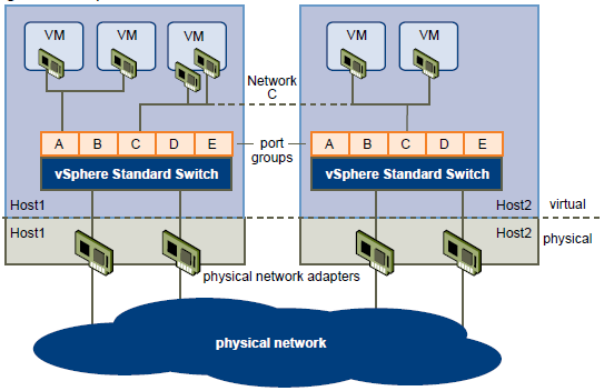
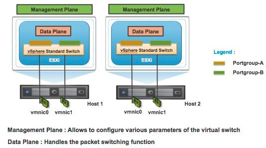
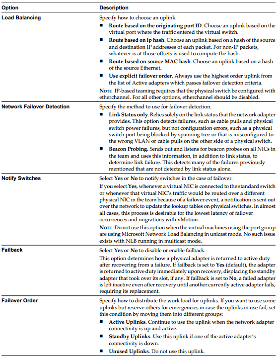
The VMware vSphere Standard Switch (VSS) is the base-level virtual networking alternative. It extends the familiar appearance, configuration, and capabilities of the standard virtual switch (vSwitch) in VMware vSphere 5.

Standard, Advanced and Enterprise License

  • Distributed Switch

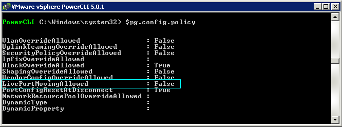
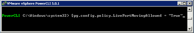
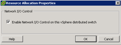
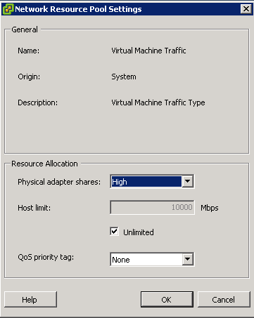
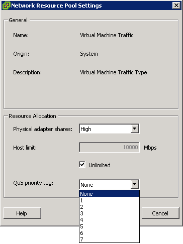
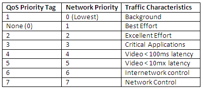
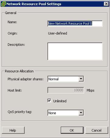
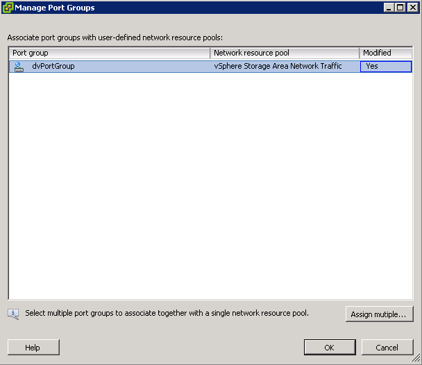
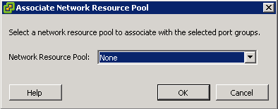
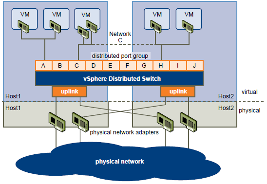
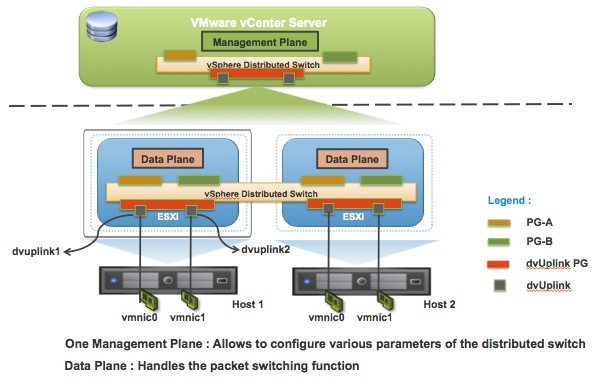
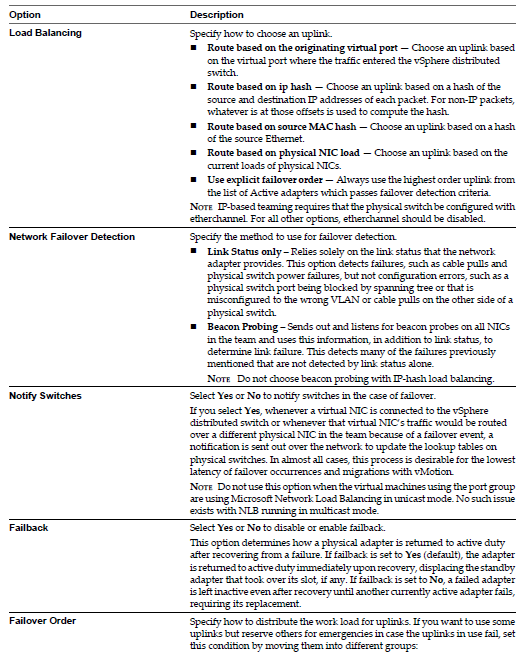
The VMware vSphere Distributed Switch (VDS) extends the feature set of the VMware Standard Switch, while simplifying network provisioning, monitoring, and management through an abstracted, single distributed switch representation of multiple VMware ESX and VMware ESXi™ Servers in a VMware data center. VMware vSphere 5 includes significant advances in virtual switching by providing monitoring, troubleshooting and enhanced NIOC features. VMware vSphere Distributed switch provides flexibility to the I/O resource allocation process by introducing User Defined network resource pools. These new features will help Network Administrators in managing and troubleshooting their virtual infrastructure using familiar tools as well as provide advanced capabilities to manage traffic granularly.

Enterprise Plus License

  • Cisco Nexus 1000v

Cisco Nexus 1000V Series Switches are the result of a Cisco and VMware collaboration building on the VMware vNetwork third-party vSwitch API of VMware VDS and the industry-leading switching technology of the Cisco Nexus Family of switches. Featuring the Cisco® NX-OS Software data center operating system, the Cisco Nexus 1000V Series extends the virtual networking feature set to a level consistent with physical Cisco switches and brings advanced data center networking, security, and operating capabilities to the VMware vSphere environment. It provides end-to-end physical and virtual network provisioning, monitoring, and administration with virtual machine-level granularity using common and existing network tools and interfaces. The Cisco Nexus 1000V Series transparently integrates with VMware vCenter™ Server and VMware vCloud™ Director to provide a consistent virtual machine provisioning workflow while offering features well suited for data center-class applications, VMware View, and other mission-critical virtual machine deployments.

Cisco Nexus 1000v is generally used in large enterprises where the management of firewalls, core- and access switches is in the control of the Network administrators. While the management of the VMware virtual Distributed Switch is in the domain of the vSphere Administrators, with a Cisco Nexus 1000v it is possible to completely separate the management of the virtual switches and hand-over to the network administrators. All this without allowing access to the rest of the vSphere platform to the Network administrators.

Cisco Licensed

  • IBM 5000V

The IBM System Networking Distributed Virtual Switch 5000V is an advanced, feature-rich distributed virtual switch for VMware environments with policy-based virtual machine (VM) connectivity. The IBM Distributed Virtual Switch (DVS) 5000V enables network administrators familiar with IBM System Networking switches to manage the IBM DVS 5000V just like IBM physical switches using advanced networking, troubleshooting and management features so the virtual switch is no longer hidden and difficult to manage.

Support for Edge Virtual Bridging (EVB) based on the IEEE 802.1Qbg standard enables scalable, flexible management of networking configuration and policy requirements per VM and eliminates many of the networking challenges introduced with server virtualization. The IBM DVS 5000V works with VMware vSphere 5.0 and beyond and interoperates with any 802.1Qbg-compliant physical switch to enable switching of local VM traffic in the hypervisor or in the upstream physical switch.

IBM Licensed

Cisco Document comparing all 3 switches except IBM

http://www.cisco.com

IBM 5000V Overview Document

http://www-03.ibm.com

Configure Live Port Moving

PG

What is Live Port Moving?

The live port moving policy allows an active port to be migrated into a dvPortGroup without dropping the connection while acquiring the settings of the target dvPortGroup. Some people say that as far as they can tell, like many advanced features, this cannot be set from within the vSphere client for a distributed port group. There is a lack of information on this subject so this is the best I can see at the moment

Edit Advanced dvPort Group Properties

Use the dvPort Group Properties dialog box to configure advanced dvPort group properties such as port override settings.

  • In the vSphere Client, display the Networking inventory view and select the dvPort group.
  • From the Inventory menu, select Network > Edit Settings.
  • Select Advanced to edit the dvPort group properties.
  • Select Allow override of port policies to allow dvPort group policies to be overridden on a per-port level.
  • Click Edit Override Settings to select which policies can be overridden.
  • Choose whether to allow live port moving.
  • Select Configure reset at disconnect to discard per-port configurations when a dvPort is disconnected from a virtual machine
  • Click OK.

dvs

PowerShell example

This is a rough example to show you where some settings are that show Live Port Moving

  • Open PowerCLI as an Administrator
  • Connect to your vCenter
  • To see the properties associated with the Get-View command type the following (See screenprint)
  • We are interested in Config

port moving1

  • In order to get into the config, we will type our previous command into a variable

port moving2

  • Now we can delve deeper into the properties of our variable by typing $pg.config

port moving 3

  • We then need to access the Policy property so type $pg.config.policy

port moving 4

  • Now we can see the LivePortMovingAllowed property
  • To change this to true, type the following below

port moving 6

Useful PowerShell Script

http://thefoglite.com/2012/07/18/configure-live-port-moving-vsphere-5/

Configure and Administer vSphere Network I/O Control

The-Traffic-Light

What is Network I/O Control?

Network I/O Control enables distributed switch traffic to be divided into different resource pools using Shares and Limits to control traffic priority applicable to a hosts outbound network I/O traffic only

Network resource pools determine the bandwidth that different network traffic types are given on a vSphere distributed switch.
When network I/O control is enabled, distributed switch traffic is divided into the following predefined network resource pools:

  • Fault Tolerance traffic
  • iSCSI traffic (Does not apply on a dependent hardware adapter)
  • vMotion traffic
  • Management traffic
  • vSphere Replication (VR) traffic
  • NFS traffic
  • Virtual machine traffic.

You can also create custom user defined network resource pools for Virtual Machine traffic

vSphere Replication

vSphere Replication is a new alternative for the replication of virtual machines. VR is introduced in vSphere Site Recovery Manager. VR is an engine that provides replication of virtual machine disk files. VR tracks changes to virtual machines and ensures that blocks that differ in a specified recovery point objective are replicated to a remote site

Configuring System Defined network Resource Pools

  • Select Home > Inventory > Networking
  • Select the Distributed Switch in the inventory and click the Resource Allocation tab
  • Click the Properties link and select Enable Network I/O Control on this vDS

Capture1

To enable network resource pool settings

  • Select the vDS
  • On the Resource Allocation Tab, right click the network resource pool and click Edit
  • Modify the physical adapter shares value and host limit for the network resource pool

Capture1

  • (Optional) Select the QoS priority tag from the drop down menu. The Qos priority tag specifies an IEE 802.1p tag enabling Quality of Service at the MAC level

Capture

  • Click OK

qos

Configuring User Defined Network Resource Pools

  • Click New Network Resource Pool
  • Put a Name
  • Put a Description
  • Choose an option in the drop-down for Physical Adapter Shares. Options are: High, Normal, Low or a Custom value.
  • Select Unlimited or not
  • Choose a level for QoS Priority Tag

Capture

Assign Port Groups to Network Resource Pools

  • Make sure you have created your own Network Resource Pool first
  • Click Manage Port Groups
  • Select a Network Resource Pool to associate with each Port Group

Capture

  • You can assign multiple Port Groups to the same Network Resource Pool

Capture

Describe the relationship between vDS and vSS

images

vSphere Standard Switch Architecture

You can create abstracted network devices called vSphere standard switches. A standard switch can..

  1. Route traffic internally between virtual machines and link to external networks
  2. Combine the bandwidth of multiple network adaptors and balance communications traffic among them.
  3. Handle physical NIC failover.
  4. Have a default number of logical ports which for a standard switch is 120. You can
  5. Connect one network adapter of a virtual machine to each port. Each uplink adapter associated with a standard switch uses one port.
  6. Each logical port on the standard switch is a member of a single port group.
  7. Have one or more port groups assigned to it.
  8. When two or more virtual machines are connected to the same standard switch, network traffic between them is routed locally. If an uplink adapter is attached to the standard switch, each virtual machine can access the external network that the adapter is connected to.
  9. vSphere standard switch settings control switch-wide defaults for ports, which can be overridden by port group settings for each standard switch. You can edit standard switch properties, such as the uplink configuration and the number of available ports.

Standard Switch

standardswitch

vSphere Distributed Switch Architecture

A vSphere distributed switch functions as a single switch across all associated hosts. This enables you to set network configurations that span across all member hosts, and allows virtual machines to maintain consistent network configuration as they migrate across multiple hosts

Like a vSphere standard switch, each vSphere distributed switch is a network hub that virtual machines can use.

  • Enterprise Plus Licensed feature only
  • VMware vCenter owns the configuration of the distributed switch
  • Distributed switches can support up to 350 hosts
  • You configure a Distributed switch on vCenter rather than individually on each host
  • Provides support for Private VLANs
  • Enable networking statistics and policies to migrate with VMs during vMotion
  • A distributed switch can forward traffic internally between virtual machines or link to an external network by connecting to physical Ethernet adapters, also known as uplink adapters.
  • Each distributed switch can also have one or more distributed port groups assigned to it.
  • Distributed port groups group multiple ports under a common configuration and provide a stable anchor point for virtual machines connecting to labeled networks.
  • Each distributed port group is identified by a network label, which is unique to the current datacenter. A VLAN ID, which restricts port group traffic to a logical Ethernet segment within the physical network, is optional.
  • Network resource pools allow you to manage network traffic by type of network traffic.
  • In addition to vSphere distributed switches, vSphere 5 also provides support for third-party virtual switches.

vdsswitch

TCP/IP Stack at the VMkernel Level

The VMware VMkernel TCP/IP networking stack provides networking support in multiple ways for each of the services it handles.

The VMkernel TCP/IP stack handles iSCSI, NFS, and vMotion in the following ways for both Standard and Distributed Virtual Switches

  • iSCSI as a virtual machine datastore
  • iSCSI for the direct mounting of .ISO files, which are presented as CD-ROMs to virtual machines.
  • NFS as a virtual machine datastore.
  • NFS for the direct mounting of .ISO files, which are presented as CD-ROMs to virtual machines.
  • Migration with vMotion.
  • Fault Tolerance logging.
  • Port-binding for vMotion interfaces.
  • Provides networking information to dependent hardware iSCSI adapters.
  • If you have two or more physical NICs for iSCSI, you can create multiple paths for the software iSCSI by configuring iSCSI Multipathing.

Data Plane and Control Planes

vSphere network switches can be broken into two logical sections. These are the data plane and the management plane.

  • The data plane implements the actual packet switching, filtering, tagging, etc.
  • The management plane is the control structure used to allow the operator to configure the data plane functionality.
  • With the vSphere Standard Switch (VSS), the data plane and management plane are each present on each standard switch. In this design, the administrator configures and maintains each VSS on an individual basis.

Virtual Standard Switch Control and Data Plane

Planes

With the release of vSphere 4.0, VMware introduced the vSphere Distributed Switch. VDS eases the management burden of per host virtual switch configuration by treating the network as an aggregated resource. Individual host-level virtual switches are abstracted into a single large VDS that spans multiple hosts at the Datacenter level. In this design, the data plane remains local to each VDS, but the management plane is centralized with vCenter Server acting as the control point for all configured VDS instances.

Virtual Distributed Switch Control and Data Plane

planes2

Configure Explicit Failover to conform with VMware Best Practice

dilbert

Best Practices

  • When configuring load balancing on the physical switch, some switches require that both interfaces be sourced to the same switch. Check with your vendor, but ideally, you should separate pNIC connections on separate switches just like you do with separate buses for a network team
  • When a failover or fallback event occurs, the delay may sever communication. To speed up the process of bringing the port online, you may want to enable portfast on your pSwitch uplinks to the ESXi host. Portfast avoids the unnecessary negotiation that takes place when a port tries to determine what it is connected to on the other end
  • Separate VM traffic and infrastructure traffic (vMotion, NFS, iSCSI)
  • Use separate pNICs and vSwitches where possible
  • VLANs can be used to isolate traffic(both from a broadcast and security perspective)
  • When using NIC teams use pNICs from separate buses (ie don’t have a team comprising two pNICs on the same PCI card – use one onboard adapter and one from an expansion card)
  • Keep FT logging on a separate pNIC and vSwitch(ideally 10GB)
  • Use dedicated network infrastructure (physical switches etc) for storage (iSCSI and NFS)
  • Use consistent port names on VLANs for virtual machine networks on all ESXi hosts
  • Every physical network adapter connected to the same vSphere standard switch or vSphere distributed switch should also be connected to the same physical network.
  • Configure all VMkernel network adapters to the same MTU. When several VMkernel network adapters are connected to vSphere distributed switches but have different MTUs configured, you might experience network connectivity problems
  • Under NIC Teaming > Network Failover Detection, Do not set to beacon probing if using route based on IP-hash
  • Notify Switches, this should be set to No if you are using Microsoft NLB in Unicast Mode
  • The Failback setting must be set to No if using IP based storage.  This is because if the link were to go up and down quickly it could have a negative impact on iSCSI traffic performance. Best practice is to leave this set to yes if not

Identify common network protocols

protocol

What is a Network Protocol?

A network protocol defines rules and conventions for communication between network devices. Protocols for computer networking all generally use packet switching techniques to send and receive messages in the form of packets.

Network protocols include mechanisms for devices to identify and make connections with each other, as well as formatting rules that specify how data is packaged into messages sent and received. Some protocols also support message acknowledgement and data compression designed for reliable and/or high-performance network communication. Hundreds of different computer network protocols have been developed each designed for specific purposes and environments.

In modern protocol design, protocols are “layered” according to the OSI 7 layer model or a similar layered model. Layering is a design principle which divides the protocol design into a number of smaller parts, each part accomplishing a particular sub-task and interacting with the  other parts of the protocol only in a small number of well-defined ways. Layering allows the parts of a protocol to be designed and tested while keeping each design relatively simple. Layering also permits familiar protocols to be adapted to unusual circumstances

Common Network protocols

  • Fibre Channel network protocols
  • Internet Protocol Suite or TCP/IP model or TCP/IP stack (TCP/UDP)
  • OSI protocols family of information exchange standards developed jointly by the ISO and the ITU-T
  • Routing protocols EIGRP, OSPF and BGP
  • List of IP protocol numbers, protocol numbers used in the Protocol field of the IPv4 header and the Next Header field of IPv6 header
  • RTPS protocol, an interoperability protocol
  • SSH Secure Shell
  • FTP File Transfer Protocol
  • SMTP Simple Mail Transfer Protocol
  • Telnet Telephone Network
  • HTTP Hyper Text Transfer Protocol
  • HTTPS Secure Hyper Text Transfer Protocol
  • SFTP Secure File Transfer Protocol
  • SSL Secure Socket Layer
  • TLS Transport Layer Security
  • POP post office protocol
  • ARP Address Resolution Protocol
  • ICMP Internet Control Mangement Protocol
  • H.323 Real-time transfer of audio and video data over packet networks
  • SNMP Monitor network availability and performance
  • SOCKS Allow clients to communicate with proxy servers (or VPN servers) through network firewalls.
  • NTP Network Time Protocol
  • CDP Cisco Discovry Protocol
  • LLDP Link Layer Discovery Protocol
  • NNTP Network News Transfer Protocol
  • Telnet
  • SSH Secure Shell
  • DNS

NIC Teaming Protocols used in vSphere

Etherchannel

EtherChannel technologies create a single logical link by bundling multiple physical Ethernet-based links (such as Gigabit Ethernet or Ten Gigabit Ethernet links) together. As such, EtherChannel links can provide for increased redundancy, capacity, and load-balancing. To optimize the load balancing of traffic over multiple links, it is recommended to deploy EtherChannels in powers of two (two, four, or eight) physical links. EtherChannel links can operate at either L2 or L3

EtherChannel links can be created using Cisco Port Aggregation Protocol (PAgP), which performs a negotiation prior to forming a channel, to ensure compatibility and administrative policies.   You can configure PAgP in four channeling modes:

  • On: Forces the LAN port to channel unconditionally. In the on mode, a usable EtherChannel exists only when a LAN port group in the on mode is connected to another LAN port group in the on mode. Ports configured in the on mode do not negotiate to form EtherChannels: They just do or do not, depending on the other port’s configuration.
  • Off: Precludes the LAN port from channeling unconditionally.
  • Desirable: Places a LAN port into an active negotiating state in which the port initiates negotiations with other LAN ports to form an EtherChannel by sending PAgP packets. A port in this mode forms an EtherChannel with a peer port that is in either auto or desirable PAgP mode.
  • Auto: (Default) Places a LAN port into a passive negotiating state in which the port responds to PAgP packets it receives but does not initiate PAgP negotiation. A port in this mode forms an EtherChannel with a peer port that is in desirable PAgP mode (only)

LACP

Alternatively, EtherChannels can be negotiated with the IEEE 802.3ad Link Aggregation Control Protocol (LACP), which similarly allows a switch to negotiate an automatic bundle by sending LACP packets to the peer. LACP supports two channel negotiation modes:

  • Active: Places a port into an active negotiating state in which the port initiates negotiations with other ports by sending LACP packets. A port in this mode forms a bundle with a peer port that is in either active or passive LACP mode.
  • Passive: (Default) Places a port into a passive negotiating state in which the port responds to LACP packets it receives but does not initiate LACP negotiation. A port in this mode forms a bundle with a peer port that is in active LACP mode (only).

Similar to PAgP, LACP requires only a single command on the physical interface when configured as a L2 link. Optionally, you can change the LACP mode from the default “passive” negotiation mode

Note that PAgP and LACP do not interoperate with each other; ports configured to use PAgP cannot form EtherChannels with ports configured to use LACP, and can ports configured to use LACP cannot form EtherChannels with ports configured to use PAgP.   EtherChannel plays a critical role in provisioning network link redundancy, especially at the campus distribution and core layers. Furthermore, an evolution of EtherChannel technology plays a key role the Cisco Virtual Switching System

Understand the NIC Teaming failover types and related physical network settings

etherchannel

What is Network Teaming and Load Balancing?

Network Teaming is the process of combining NICs to provide bandwidth and failover to a switch. Load balancing and failover policies allow you to determine how network traffic is distributed between network adapters and how to re-route traffic in the event of adapter failure.

You can set NIC Teaming on the following objects

  • Standard Switch
  • Distributed Switch
  • Standard Port Group
  • Distributed Port Group

Settings Overview for a Standard Switch

portgroup_network_policies

Procedure for a Standard Switch and a Standard Port Group

  • Log in to the vSphere Client and select the server from the inventory panel.
    The hardware configuration page for this server appears.
  • Click the Configuration tab and click Networking.
  • Select a Standard Switch or Standard Port Group and click Edit.
  • Click the Ports tab.
  • To edit the Failover and Load Balancing values, select the standard switch item and click Properties.
  • Click the NIC Teaming tab
  • You can override the failover order at the port group level. By default, new adapters are active for all policies. New adapters carry traffic for the standard switch and its port group unless you specify otherwise.

Specify how to choose an uplink.

  • Route based on the originating virtual port
  1. Choose an uplink based on the virtual port where the traffic entered the distributed switch. This is the default configuration and the one most commonly deployed.
  2. When you use this setting, traffic from a given virtual Ethernet adapter is consistently sent to the same physical adapter unless there is a failover to another adapter in the NIC team.
  3. Replies are received on the same physical adapter as the physical switch learns the port association.
  4. This setting provides an even distribution of traffic if the number of virtual Ethernet adapters is greater than the number of physical adapters.
  5. A given virtual machine cannot use more than one physical Ethernet adapter at any given time unless it has multiple virtual adapters.
  6. This setting places slightly less load on the ESX Server host than the MAC hash setting.
  • Route based on ip hash
  1. Choose an uplink based on a hash of the source and destination IP addresses of each packet. For non-IP packets, whatever is at those offsets is used to compute the hash.
  2. Evenness of traffic distribution depends on the number of TCP/IP sessions to unique destinations. There is no benefit for bulk transfer between a single pair of hosts.
  3. You can use link aggregation — grouping multiple physical adapters to create a fast network pipe for a single virtual adapter in a virtual machine.
  4. When you configure the system to use link aggregation, packet reflections are prevented because aggregated ports do not retransmit broadcast or multicast traffic.
  5. The physical switch sees the client MAC address on multiple ports. There is no way to predict which physical Ethernet adapter will receive inbound traffic.
  6. All adapters in the NIC team must be attached to the same physical switch or an appropriate set of stacked physical switches. (Contact your switch vendor to find out whether 802.3ad teaming is supported across multiple stacked chassis.) That switch or set of stacked switches must be 802.3ad-compliant and configured to use that link-aggregation standard in static mode (that is, with no LACP).
  7. All adapters must be active. You should make the setting on the virtual switch and ensure that it is inherited by all port groups within that virtual switch
  • Route based on source MAC hash
  1. Choose an uplink based on a hash of the source Ethernet MAC Address
  2. When you use this setting, traffic from a given virtual Ethernet adapter is consistently sent to the same physical adapter unless there is a failover to another adapter in the NIC team.
  3. Replies are received on the same physical adapter as the physical switch learns the port association.
  4. This setting provides an even distribution of traffic if the number of virtual Ethernet adapters is greater than the number of physical adapters.
  5. A given virtual machine cannot use more than one physical Ethernet adapter at any given time unless it uses multiple source MAC addresses for traffic it sends.
  • Use explicit failover order

Always use the highest order uplink from the list of Active adapters which passes failover detection criteria.

NOTE IP-based Hash teaming requires that the physical switch be configured with etherchannel. For all other options, etherchannel should be disabled.

Settings Overview for a Distributed Switch

Capture

Procedure for a Distributed Switch and a Distributed Port Group

  • Log in to the vSphere Client and select the server from the inventory panel. The hardware configuration page for this server appears.
  • Click the Configuration tab and click Networking.
  • Select a Distributed Switch or Distributed Port Group and click Edit.
  • Click the Ports tab.
  • To edit the Failover and Load Balancing values, select the standard switch item and click Properties.
  • Click the NIC Teaming tab
  • You can override the failover order at the port group level. By default, new adapters are active for all policies. New adapters carry traffic for the standard switch and its port group unless you specify otherwise.

Specify how to choose an uplink.

  • Route based on the originating virtual port
  1. Choose an uplink based on the virtual port where the traffic entered the distributed switch. This is the default configuration and the one most commonly deployed.
  2. When you use this setting, traffic from a given virtual Ethernet adapter is consistently sent to the same physical adapter unless there is a failover to another adapter in the NIC team.
  3. Replies are received on the same physical adapter as the physical switch learns the port association.
  4. This setting provides an even distribution of traffic if the number of virtual Ethernet adapters is greater than the number of physical adapters.
  5. A given virtual machine cannot use more than one physical Ethernet adapter at any given time unless it has multiple virtual adapters.
  6. This setting places slightly less load on the ESX Server host than the MAC hash setting.
  • Route based on ip hash
  1. Choose an uplink based on a hash of the source and destination IP addresses of each packet. For non-IP packets, whatever is at those offsets is used to compute the hash.
  2. Evenness of traffic distribution depends on the number of TCP/IP sessions to unique destinations. There is no benefit for bulk transfer between a single pair of hosts.
  3. You can use link aggregation — grouping multiple physical adapters to create a fast network pipe for a single virtual adapter in a virtual machine.
  4. When you configure the system to use link aggregation, packet reflections are prevented because aggregated ports do not retransmit broadcast or multicast traffic.
  5. The physical switch sees the client MAC address on multiple ports. There is no way to predict which physical Ethernet adapter will receive inbound traffic.
  6. All adapters in the NIC team must be attached to the same physical switch or an appropriate set of stacked physical switches. (Contact your switch vendor to find out whether 802.3ad teaming is supported across multiple stacked chassis.) That switch or set of stacked switches must be 802.3ad-compliant and configured to use that link-aggregation standard in static mode (that is, with no LACP).
  7. All adapters must be active. You should make the setting on the virtual switch and ensure that it is inherited by all port groups within that virtual switch
  • Route based on source MAC hash
  1. Choose an uplink based on a hash of the source Ethernet MAC Address
  2. When you use this setting, traffic from a given virtual Ethernet adapter is consistently sent to the same physical adapter unless there is a failover to another adapter in the NIC team.
  3. Replies are received on the same physical adapter as the physical switch learns the port association.
  4. This setting provides an even distribution of traffic if the number of virtual Ethernet adapters is greater than the number of physical adapters.
  5. A given virtual machine cannot use more than one physical Ethernet adapter at any given time unless it uses multiple source MAC addresses for traffic it sends.
  • Route based on physical NIC Load
  1. Load based teaming uses the same inital port assignment as the “Originating Port ID” policy. The first virtual NIC is affiliated to the first physical NIC, the second virtual NIC to the second physical NIC etc. After initial placement, load based teaming examines both ingress and egress load of each uplink in the team. Load based teaming then adjusts the virtual NIC to Physical mapping if an uplink is congested. the NIC team load balancer flagas a congestion condition of an uplink experiences a mean use of 75% or more over a 30 second period
  • Use explicit failover order

Always use the highest order uplink from the list of Active adapters which passes failover detection criteria.

NOTE: IP-based Hash teaming requires that the physical switch be configured with etherchannel. For all other options, etherchannel should be disabled.

Further Information on Route based on the originating Port ID

it’s important to understand the basic behavior in this configuration. Because the vSwitch is set to “Route based on originating virtual port ID”, network traffic will be placed onto a specific uplink and won’t use any other uplinks until that uplink fails. Every VM and every VMkernel port gets its own virtual port ID. These virtual port IDs are visible using esxtop (launch esxtop, then press “n” to switch to network statistics)

  • Each VM will only use a single network uplink, regardless of how many different connections that particular VM may be handling. All traffic to and from that VM will be place on that single uplink, regardless of how many uplinks are configured on the vSwitch.
  • Each VMkernel NIC will only use a single network uplink. This is true both for VMotion as well as IP-based storage traffic, and is true regardless of how many uplinks are configured on the vSwitch.
  • Even when the traffic patterns are such that using multiple uplinks would be helpful—for example, when a VM is copying data to or from two different network locations at the same time, or when a VMkernel NIC is accessing two different iSCSI targets—only a single uplink will be utilized.
  • It’s unclear at what point VMware ESX creates the link between the virtual port ID and the uplink. In tests, rebooting the guest OS and power cycling the VM results in  having it come back on the same uplink again. Only a VMotion off the server and back again caused a VM to move to a new uplink.
  • There is no control over the placement of VMs onto uplinks without the use of multiple port groups. (Keep in mind that you can have multiple port groups corresponding to a single VLAN.)
  • Because multiple VMs could be assigned to the same uplink, and because users have no control over the placement of VMs onto uplinks, it’s quite possible for multiple VMs to be assigned to the same uplink, or for VMs to distributed unevenly across the uplinks. Organizations that will have multiple “network heavy hitters” on the same host and vSwitch may run into situations where those systems are all sharing the same network bandwidth.

These considerations are not significant, but they are not insignificant, either. The workaround for the potential problems outlined above involves using multiple port groups with different NIC failover orders so as to have more fine-grained control over the placement of VMs on uplinks. In larger environments, however, this quickly becomes unwieldy. The final release of the Distributed vSwitch will help ease configuration management in this sort of situation.

Useful Blogs on VMware NIC Teaming. (Thanks to Scott Lowe)

http://blog.scottlowe.org/2008/10/08/more-on-vmware-esx-nic-utilization/
http://blog.scottlowe.org/2008/07/16/understanding-nic-utilization-in-vmware-esx/

Use command line tools to troubleshoot and identify VLAN configurations

images

Valid Commands

Note: With the release of 5.0, the majority of the legacy esxcfg-*/vicfg-* commands have been migrated over to esxcli. At some point, hopefully not in the distant future, esxcli will be parity complete and the esxcfg-*/vicfg-* commands will be completely deprecated and removed including the esxupdate/vihostupdate utilities.

  • esxcfg-nics
  • vicfg-nics
  • esxcfg-route
  • vicfg-route
  • esxcfg-vmknic
  • vicfg-vmknic
  • esxcfg-vswitch
  • vicfg-vswitch
  • esxcli network nic
  • esxcli network interface
  • esxcli network vswitch
  • esxcli network ip

What to use When

cli

Examples

DCUI

You can also either connect to the console screen to look at Network Settings or connect via Putty/vMA/vCLI and type DCUI to get the following screen

DCUI

 ESXCLI and VICFG

Retrieving Network Port Information

nic2

Setting Virtual Switch Attributes

nic3

Listing, Creating and Deleting Standard Switches

nic4

Managing a VMKernel Port

nic5

Listing, Adding and Removing Port Groups

nic6

Configuring a PortGroup with a VLAN ID

nic7

Linking and Unlinking Uplink Adapters

nic8

Configure DNS and Routing

nic10

Managing uplinks in Distributed switches

nic13

Command Line reference

http://pubs.vmware.com

Command Line Interface – Getting Started

vCLI Poster of example commands

http://blogs.vmware.com