Tag Archive for VMware

What’s going on with VMware Transparent Page Sharing?


What is Transparent Page Sharing?

When multiple virtual machines are running, some of them may have identical sets of memory content. This presents opportunities for sharing memory across virtual machines (as well as sharing within a single virtual machine). For example, several virtual machines may be running the same guest operating system, have the same applications, or contain the same user data. With page sharing, the hypervisor can reclaim the redundant copies and keep only one copy, which is shared by multiple virtual machines in the host physical memory. As a result, the total virtual machine host memory consumption is reduced and a higher level of memory overcommitment is possible.

What is the security problem related to Transparent Page Sharing currently?

There has been recent academic research that leverages Transparent Page Sharing (TPS) to gain unauthorized access to data under certain highly controlled conditions and documents VMware’s precautionary measure of restricting TPS to individual virtual machines by default in upcoming ESXi releases. At this time, VMware believes that the published information disclosure due to TPS between virtual machines is impractical in a real world deployment.

Published academic papers have demonstrated that by forcing a flush and reload of cache memory, it is possible to measure memory timings to try and determine an AES encryption key in use on another virtual machine running on the same physical processor of the host server if Transparent Page Sharing is enabled between the two virtual machines. This technique works only in a highly controlled system configured in a non-standard way that VMware believes would not be recreated in a production environment. .

Even though VMware believes information being disclosed in real world conditions is unrealistic, out of an abundance of caution upcoming ESXi Update releases will no longer enable TPS between Virtual Machines by default (Inter-VM TPS). TPS will still be utilized within individual VMs. (Intra-VM TPS)

What is meant by Intra-VM and Inter-VM in the context of Transparent Page Sharing?

  • Intra-VM means that TPS will de-duplicate identical pages of memory within a virtual machine, but will not share the pages with any other virtual machines.
  • Inter-VM mean that TPS will de-duplicate identical pages of memory within a virtual machine and will also share the duplicates with one of more other virtual machines with the same content.

VMware will disable the ability to share memory pages “between” virtual machines (Inter-VM Transparent Page Sharing) by default (in ESXi 5.0/5.1 and 5.5) in coming updates and the next major ESXi release and inter-Virtual Machine TPS is not enabled by default as of ESXi 6.0. Administrators may revert to the previous behavior if they so wish.

What could potentially be the effect?

Disabling inter-Virtual Machine TPS may impact performance in environments that rely heavily on memory over-commitment although we still have memory resource management techniques such as

  • Ballooning – Reclaims memory by artificially increasing the memory pressure inside the guest
  • Hypervisor/Host swapping – Reclaims memory by having ESX directly swap out the virtual machine’s memory
  • Memory Compression – Reclaims memory by compressing the pages that need to be swapped out

Please keep reading KB52337 for further information

So what options do we have?

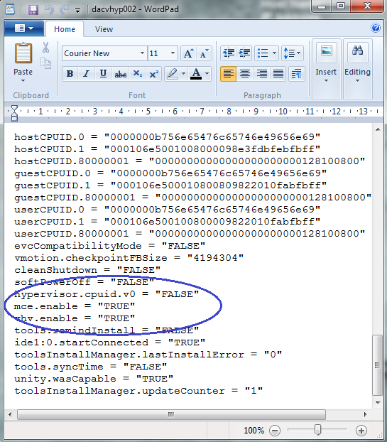
The concept of salting has been introduced to help address concerns system administrators may have over the security implications of TPS. Salting is used to allow more granular management of the virtual machines participating in TPS than was previously possible. As per the original TPS implementation, multiple virtual machines could share pages when the contents of the pages were same. With the new salting settings, the virtual machines can share pages only if the salt value and contents of the pages are identical. A new host config option Mem.ShareForceSalting is introduced to enable or disable salting.

By default, salting is enabled after the ESXi update releases mentioned above are deployed, (Mem.ShareForceSalting=2) and each virtual machine has a different salt. This means page sharing does not occur across the virtual machines (inter-VM TPS) and only happens inside a virtual machine (intra VM).

When salting is enabled (Mem.ShareForceSalting=1 or 2) in order to share a page between two virtual machines both salt and the content of the page must be same. A salt value is a configurable vmx option for each virtual machine. You can manually specify the salt values in the virtual machine’s vmx file with the new vmx option sched.mem.pshare.salt. If this option is not present in the virtual machine’s vmx file, then the value of vc.uuid vmx option is taken as the default value. Since the vc.uuid is unique to each virtual machine, by default TPS happens only among the pages belonging to a particular virtual machine (Intra-VM).
If a group of virtual machines are considered trustworthy, it is possible to share pages among them by setting a common salt value for all those virtual machines (inter-VM).

The following table shows how different settings for TPS are used together to affect how TPS operates for individual virtual machines: 

What is the default behavior of Transparent Page Sharing in above mentioned Update releases?

By default, the setting is (Mem.ShareForceSalting=2) and each virtual machine has a different salt (that is sched.mem.pshare.salt is not present) which means that only Intra-VM page sharing is enabled. This behavior is new as per these ESXi update releases and page sharing will not happen across the virtual machines (inter-VM TPS) by default. 

How can I enable or disable salting? 

  1. Log in to ESX (i)/vCenter with the VI-Client.
  2. Select ESX (i) relevant host.
  3. In the Configuration tab, click Advanced Settings (link) under the software section.
  4. In the Advanced Settings window, click Mem.
  5. Search for Mem.ShareForceSalting and set the value to 1 or 2 (enable salting), 0 (disable salting).
  6. Click OK.
  7. For the changes to take effect do either of the two:
    • Migrate all the virtual machines to another host in cluster and then back to original host. Or
    • Shutdown and power-on the virtual machines.

How can I allow inter-VM TPS between two or more virtual machines?

Inter-VM TPS is enabled for two or more virtual machines by enabling salting and by giving them the same salt value.

How can I specify salt value of a virtual machine?

  1. Power off the virtual machine on which you want to set salt value.
  2. Right click on virtual machine, click on Edit settings.
  3. Select options menu, click on General under Advanced section.
  4. Click on Configuration Parameters
  5. Click on Add Row, new row will be added.
  6. On LHS add text sched.mem.pshare.salt and on RHS specify the unique string.
  7. Power on the virtual machine to take effect of salting.
  8. Repeat steps 1 to 7 to set the salt value for individuals virtual machine.

What is the difference in behavior of page sharing when MEM_SHARE_FORCE_SALTING value is set to 1 and 2?

MEM_SHARE_FORCE_SALTING 1: By default salt value is taken from sched.mem.pshare.salt. If not specified, falls back to old TPS (inter-VM) behavior by considering salt values for the virtual machine as 0.

MEM_SHARE_FORCE_SALTING 2: By default salt value is taken from vc.uuidz. If it does not exist, then the page sharing algorithm generates random and unique value for salting per virtual machine, which is not configurable by users.

How can I prepare for the ESXi Update releases that no longer allow inter-VM TPS by default?

VMware recommends you to monitor free memory available on the host along with the total ballooned and total swapped memory before deploying the ESXi update releases listed above that disallow inter-VM TPS. Once inter-VM TPS is disallowed, available free memory might drop which further can lead to increased ballooning and swapping. If increased ballooning and swapping activity is observed along with noticeable performance issues, more physical memory can be added on the host or the memory load on the host can be reduced.
To monitor the stats – Run esxtop command:

  • Run esxtop on host, click to switch to memory mode.
  • free from PMEM /MB row displays the free memory available on the host.
  • curr from MEMCTL/MB row displays the total ballooned memory.
  • curr from SWAP/MB row displays the total swapped memory.

How can I enable or disable salting for multiple ESXi hosts?

To enable or disable salting for multiple ESXi hosts. Refer to the attached powercli script in KB2097593

. This script allows toggling pshare salting for update releases.

Usage

.\pshare-salting.ps1 <vcenter IP/hostname> -s -> Enables pshare salting.
.\pshare-salting.ps1 <vcenter IP/hostname> -o -> Turn offs pshare salting and falls back to default TPS behaviour

Links

KB2080735

KB2097593

Are there any tools we are able to use to compare TPS savings before and after disabling Inter-VM transparent page sharing?

There is a PowerShell script (VMware recommended) called the “Host Memory Assessment Tool” to look at shared memory per host, and report it in a tabular form, so you can easily review the current shared memory savings, and the worst case impact in contrast with the free memory on the host. The script uses plink.exe to remotely SSH into each ESXi host and record memory counters using vsish. There is very low risk and impact to the ESXi hosts as it is a read only process

https://www.brianjgraf.com/2015/04/03/assess-impact-tps-vsphere-6/

What the script does:

  • Connects to vCenter and enumerates all ESXi hosts
  • Allows you to enable SSH on selected hosts
  • Generates an assessment report
  • Allows you to export the assessment report to .csv
  • Allows you to easily turn off SSH again if necessary

This tool would need to be run on an normal existing system with workloads with TPS on and Off to see the different outputs.

https://www.brianjgraf.com/2015/04/03/assess-impact-tps-vsphere-6/

VMware Update (20/03/2018)

The last update and updates going forward on performance impact associated with applying the security patches are now found in https://kb.vmware.com/s/article/52337

Virtualization Layer Mitigations: The latest ESXi patches** and the relevant Intel CPU microcode but without Guest Operating System mitigation patches. These mitigations have a minimal performance impact (< 2%) for most workloads on a representative range of recent Intel Xeon server processors.

Full Stack Mitigations: All levels of mitigation. This includes all virtualization layer mitigations above with the addition of Guest Operating System mitigation patches. As reported in the press, the impact of these mitigations will vary depending on your application. Applications with very heavy system call usage, including those with very high IO rates, will show a more significant impact than their counterparts with lower system call usage. For information regarding the performance impact of Operating System Mitigations on your application, please consult with your Operating system and/or Application vendor. Consistent with our findings above, the virtualization layer mitigations that are part of these full stack mitigations have minimal influence to the overall impact. As a general best practice, we recommend you test the appropriate patches with your applications prior to deploying in production environments.

VMware vRealize Automation 6.2.2 Configuration and Management Part 5

vRARobot

Cost Profiles

Fabric administrators can associate compute resources and physical machines with cost profiles to enable calculation of a machine’s cost. The cost is displayed to machine owners, requesters, approvers, and administrators at various points in the request and provisioning life cycle.

A cost profile includes the following values for daily cost:

Cost per GB of memory capacity specified in the virtual blueprint or installed in the physical machine

Cost per CPU specified in the virtual blueprint or installed in the physical machine

Cost per GB of storage capacity as specified in the virtual blueprint (not used for physical machines, because storage attached to physical machines is not discovered or tracked)

For finer definition of storage cost for virtual machines, you can also associate each known datastore on a compute resource with a storage cost profile. A storage cost profile contains only a daily cost per GB of storage. If you assign a storage cost profile to a datastore, this storage cost overrides the storage cost in the cost profile assigned to the compute resource.

For virtual machines, the machine cost is calculated from the cost profile and storage cost profile on the compute resource, the resources it consumes, and the daily blueprint cost. You can use the blueprint cost to represent a markup for using the machine in addition to the resources that the machine consumes, for example to account for the cost of specific software deployed with that blueprint.

For physical machines, the machine cost is calculated from the cost profile on the machine, the CPU and memory on the machine, and the daily blueprint cost. You can use the blueprint cost to represent such factors as storage cost or additional costs for using the machine.

You cannot apply cost profiles to machines provisioned on Amazon Web Services or Red Hat OpenStack. For machines provisioned on these cloud platforms, the only cost factor is the daily cost in the blueprint from which it was provisioned. The cost for vCloud Director vApps includes any cost profile and storage cost profile on the virtual datacenter and the blueprint cost.

Create a Cost Profile 

Fabric administrators can create cost profiles and associate them with compute resources to enable calculation of a machine’s cost.

  • Select Infrastructure > Compute Resources > Cost Profiles.

vRA70

  • Click New Cost Profile
  • Type new values in for each resource

vRA71

  • You can also add a Storage Cost Profile for storage of different performance capabilities such as High, Medium and Low cost storage

Using Custom Properties on Blueprints

You can modify a machine using custom properties throughout the lifecycle of the machine

  • Request
  • Provision
  • Manage
  • Retire

As an example they can modify the following

  • Specify the WIM image or PE environment image to use for install
  • Define the number of cores per socket
  • Place the machine in an OU
  • Place the machine in an inventory folder in vCenter
  • Change the network a machine is attached to
  • Update a CMDB

Custom properties can be defined for the following objects

  • Business Groups
  • Compute Resource
  • Build Profiles
  • Reservations
  • Endpoints
  • Blueprints
  • Storage

Useful Link

http://www.vmware.com/support/pubs/vcac-pubs.html

Set up Custom Properties

As an example I want to add a custom property to a blueprint which puts my machine in a specific folder in vCenter

  • Go to Infrastructure > Blueprints > Select your blueprint and click Edit
  • Click on the Properties tab

vRA77

  • Add in VMware.VirtualCenter.Folder and type in a name for the inventory folder in vCenter that you want to use which provisioned machines will go into. In my case I have called it vRA.
  • Next go to Infrastructure > Groups > Business Groups > Click edit on your business group

vRA78

  • Click New Property
  • Type in the name and value of your custom property.
  • Name = VMware.Virtual.Center.Folder
  • Value = vRA

vRA79

  • Go to Catalog and request a Virtual Machine again
  • Once deployed, check vCenter has deployed the machine to the vRA folder and not the vRM folder

vRA80

Add Location Information

  • Go to c:\Program Files (x86)\Vmware\vCAC\Server\Website\XmlData
  • Right click DataCenterLocations and click Edit
  • Copy the line with Boston in it and paste it underneath

vRA81

  • Change all instances of Bolton with a new location

vRA82

  • Save the file
  • Go back to your vRA webpage and go to Infrastructure > Blueprints > Blueprints
  • Click Edit on your Blueprint
  • Click the Display Location on request

vRA83

  • Click OK and logout
  • Log back in and go to Infrastructure > Compute Resources > Compute Resources
  • Click Edit
  • From the location menu click the location you want

vRA84

Other Custom Property Options

  • Hostname

This can be used to prompt a user to put in a hostname other than the ne defined by the machine prefix on the blueprint

  • VirtualMachine.Admin.ThinProvision

This option forces a new machine to be thin provisioned on the storage device

vRA85

Build Profiles

A build profile is a set of properties to be applied to a machine when it is provisioned. It can be used for the following

  • Determining the spec of a machine
  • Determine how the machine is provisioned
  • Determine the operations to be performed after the machine is provisioned
  • Manage information about the machine

Build Profiles are attached to Blueprints and the spec of the build profile is available to business group users who have access to the blueprints

Build Profiles are constructed from default property sets or custom properties. Default sets include

  • ActiveDirectoryCleanupPlugin
  • CitrixDesktopProperties
  • PxeProvisioningProperties
  • SysprepProperties
  • VmwareXXXXXProperties

Creating a Build Profile

  • Go to Infrastructure > Blueprints > Build Profiles

vRA86

  • Click New Build Profile
  • Add a name and description
  • From the Add from property set drop down list, select ActiveDirectoryCleanUpPlugin

vRA87

  • In the Plugin.AdMachineCleanup.UserName, click Edit and add the username of a domain admin. In my case dacmt\administrator
  • In the Plugin.AdMachineCleanup.Password, click Edit and add the password of a domain admin
  • Make sure you click the green tick to confirm the changes
  • Logout
  • Login again
  • Click Infrastructure > Blueprints > Blueprints
  • Click Edit on your Blueprint
  • Click the Properties tab
  • Select the Remove from AD Build build profile

vRA88

The Property Dictionary

The Property Dictionary can be used with custom properties to create a customised interface. You can statically or dynamically define the interface with the following data specification options

  • Data validation
  • Defined constraints on data values
  • Tooltip
  • Optional data
  • Ordered user control layouts

Using the Property Dictionary helps stop mistakes which occur when the data value of a custom property is passed into extensibility tools like Orchestrator and Powershell

When users request new machines they are prompted for these custom properties in the form of a required text box, drop down menu or buttons and more

  • Go to Infrastructure > Blueprints > Property Dictionary
  • On the Property Dictionary page, click New Property Definition

vRA89

  • Fill in the required details
  • Click required and then click the green arrow

vRA90

  • Click Edit under Property Attribute

vRA91

  • Click New Property Attribute

vRA92

  • Add in the below values

vRA93

  • Log off
  • Log on again and go to Infrastructure > Blueprints > Blueprints and edit your blueprint and select the Properties tab
  • Select New Property

vRA94

  • Type Custom.StorageTier in to the name an leave the value blank with Prompt user selected

vRA96

  • Click OK
  • Go to Catalog > Request your machine
  • Look at the new option you have on the interface for Storage Tier

vRA95

  • Note: vRA does not directly use storage tiering. You have to use custom properties and workflow modification with vSphere PowerCLI or Orchestrator

Approval Policies

Any catalog item or entitled action can be subject to an approval. The Approval Policies must first be defined by either a tenant administrator or a business group user and set as active before they appear in an entitlement

There can be multi levels of approvals with all different Boolean conditions as to how the policy can be approved across these levels.

Active and Linked approvals can only be cloned not edited

Creating an Approval Policy

  • Click the Administration tab > Users and Groups > Custom Groups
  • Search for the user or group you want to add as an approver

vRA98

  • Click Next
  • Add in the users who you want to be Appprovers

vRA99

  • Next go to Administration > Approval Policies

vRA101

  • Click Add

vRA102

  • Click OK
  • I am going to create a vCPU approval policy
  • Put in the name and set to Active

vRA103

  • Click the green plus sign next to Levels
  • Fill in the required information

vRA106

  • Click Add and Add again
  • Log out
  • Log in again
  • Click Administration > Catalog Management > Entitlements
  • Highlight your Blueprint and click Edit

vRA107

  • Click Items and Approvals
  • Click Entitled Catalog Items and Modify Policy

vRA108

  • Click the drop down menu and select your policy. Note apologies I had to recreate mine as CPU > 2

vRA109

  • Click on Catalog > Request and select your VM
  • Change the vCPUs to 4

vRA110

  • Click Submit
  • Now look at the Request tab where we should see the request sitting in the pending approval status

vRA111

  • If you click on the request and select view details, it will show you who is the approver

vRA112

  • Click on Inbox > Approvals as I am already logged in as myself as the approver

vRA113

  • Click View Details and select whether to Approve or Reject

vRA114

  • This concludes the configuration and management Part 5
  • Part 6 will go into more of the extensibility options like Advanced Service Designer and Orchestrator


VMware vRealize Automation 6.2.2 Configuration and Management Part 4

vRARobot2

Blueprints

Blueprints are used to define a machines attributes and methods of provisioning. These blueprints are then added into the Service Catalog ready for users to provision machines. There are 4 different types

  • Cloud
  • Physical
  • Virtual
  • Multimachine (New in vRA 6)

A user can request VMs if the below conditions are met

  • The Blueprint is published as a catalog item
  • The item is added to a service
  • The user is entitled to use the service

Configuring Blueprints

  • Go to Infrastructure -> Blueprints -> Blueprints

vRA40

  • Click New Blueprint > Virtual > vSphere (vCenter)

vRA41

  • Put in a name. I am going to call mine Windows2012Blueprint
  • Put in a description
  • (Optional) Select the Master check box to allow users to copy your blueprint.
  • (Optional) Select the Display location on request check box to prompt users to choose a datacenter location when they submit a machine request. This option requires additional configuration to add datacenter locations and associate compute resources with those locations
  • (Optional)Choose your reservation policy
  • Choose the machine prefix you have previously set up
  • Choose the maximum amount of VMs which can be deployed from this blueprint per user
  • Specify the number of days to archive machines provisioned from this blueprint, just keep it at 0 for now. Archive defines the number of days that an expired virtual machine remains available for activation. A zero value destroys the VM upon expiration
  • Add in any additional costs for chargeback purposes. These costs will be added to anything that is set in a cost profile. so you can add in a OS licensing cost or specific application cost for this VM

vRA45

  • Click Build Information
  • The build information tab options define the type of blueprint, the provisioning action and the associated workflow
  • In Blueprint type, the options are Server / Desktop / Hypervisor
  • In Action, the options are Create, Clone, Linked Clone and NetApp FlexClone. Using the Create option creates an empty container. The clone option creates a new machine as a full copy and the Linked Clone option deploys a space efficient copy based on snapshots and chains of delta disks

vRA46

  • Next the blueprint provisioning workflow option vary depending on what blueprint action you selected
  • Next we need to select a template to clone from

vRA51

  • Next Choose a customisation spec. A customization specification is required only if you are cloning with static IP addresses. However, you cannot perform any customizations of Windows machines without a customization specification object. For Linux clone machines, you can use a customization specification, an external script, or both to perform customizations.

vRA48

  • In Machine Resources, you can define the maximum and minimum resources that can be chosen by a user who wants to provision a VM from this blueprint.  It’s optional but you can specify maximum amounts of vCPU, RAM, and HDD space that can be assigned to this blue print which gives a user the ability to customize to their specific application
  • Next click the Properties tab
  • Additional information can be provided during the provisioning process using Custom Properties
  • Custom Properties can be used throughout the lifecycle of a machine

vRA49

  • Options for customising properties can include

Specifying the O/S to be used during provisioning

Customizing the O/S

Link for Custom Properties for Basic Workflow Blueprints 

http://pubs.vmware.com/vra-62/index.jsp#com.vmware.vra.iaas.virtual.doc/GUID-15B1491D-BECF-40DE-9F2C-315975476B3B.html

Integrating the machine with an external system

  • Click the Actions tab
  • Actions identify the operations that can be carried out on a VM provisioned from a blueprint with additional custom actions being defined in Advanced Services Designer and entitled to users

vRA50

  • Click OK to finish
  • You should now see your blueprint

vRA52

Publishing a Blueprint

  • Navigate to Infrastructure > Blueprints > Blueprints. Highlight your new blueprint and click on Publish to publish the blueprint to the vRA catalog

vRA53

  • You should now see that it is published

Service Catalog

The Service Catalog is a self service portal where users can locate the items they want to request and track requests and manage provisioned items.

Using Service Categories, catalog items can be organised into containers such as Linux, Windows or User Support

  •  Go to Administration > Catalog Management > Services. Click on the green “+” sign to add a new service.

vRA54

  • Fill in the required data and choose an icon as necessary to reflect the Service, in my case Windows

vRA55

  • You should now see your service

vRA56

  • Click on Manage Catalog Items. A catalog item must be associated with a service before it can be requested

vRA57

  • Click the green + sign

vRA58

  • Choose your catalog item. In my case the Windws2012 item

vRA59

Create an Entitlement to the catalog item

  • Go to Administration > Catalog Management > Entitlements and click on the green “+” mark

vRA60

  • Fill in your details

vRA61

  • Click Next
  • Click the green + sign next to Entitled Services and select your service

vRA62

  • Click the green + sign next to Entitled Catalog items and select your Catalog item

vRA63

  • Click the green + sign next to Entitled Actions and select your Actions

vRA64

  • Click OK and you should now see your entitlements

vRA65

Provision a machine

  • Go to the Catalog tab and check if your service is available

vRA66

  • Click Request
  • Check the details and modify the request reason
  • Remember you can only modify the resources up to the maximum set in the blueprint and sometimes these are subject to approval policies as well. (Which haven’t been covered yet)

vRA67

  • Click Submit and the VM should be provisioned in vCenter
  • Click the Requests tab to monitor the request

vRA68

  • If you log into vCenter and go to Virtual Machines and Templates, you will see that vCAC by default will place all provisioned machines into a vCenter folder named VRM.  You can override this using the custom property VMware.VirtualCenter.Folder to tell vRA where to place the provisioned machine.
  • My machine is dacv001

vRA69

  • If you click on the Items tab once the machine is provisioned, you can manage some actions which are controlled by entitlements

vRA72

Taking a snapshot

  • Click on Items
  • Click on the Owned by drop down menu and change this to “All groups I manage”
  • Click on View Details

vRA73

  • Click New Snapshot

vRA74

  • vRA allows one snapshot per machine and no age limits

Installing VMware vRealize Automation 6.2.2 Part 2

vRARobot

Installing VMware vRA 6.2.2

vRA is software which provides a secure portal for authorised architects, business managers and users to request IT services through a commons service catalog. Tasks vRA can perform are

  • Provisioning of machines
  • Reclamation of machines
  • Services such as adding AD users
  • Storage as a Service

vRealize Automation Support Matrix

https://www.vmware.com/pdf/vrealize-automation-62-support-matrix.pdf

VMware vRealize Automation 6.2 Documentation Center

http://pubs.vmware.com/vra-62/index.jsp

vRA Components

  • VMware Identity Appliance – Preconfigured virtual appliance. You can alternatively use some versions of SSO provided with vSphere
  • VMware vRealize Appliance – Preconfigured virtual appliance that deploys the vRealize server
  • vRealize Automation Infrastructure as a Service – Enables the rapid modelling and provisioning of servers and desktops across virtual, physical, private, public and hybrid clouds
  • SQL server Database
  • IIS Server for IAAS

vRealize Automation Infrastructure as a Service has several components you can install in a custom configuration

  • IAAS website
  • Model Manager
  • vCloud Automation Center Manager Service
  • IAAS Database
  • Distributed Execution Managers
  • vRealize Automation Agents

Types of deployment

Click the links below for further information

Let’s get started

Installing the VMware vRealize Appliance

  • Download the .ova installer from the VMware site and I saved this to my vCenter server

vRA1

  • In vCenter click File > Deploy OVF template

vRA2

  • Select your ovf file which you downloaded

vRA3

  • Click Next and you should see the following information populate

vRA4

  • Click Next and accept the license agreement

vRA5

  • Put in a name and an inventory location

vRA6

  • Choose a storage location

vRA7

  • Choose a disk layout

vRA8

  • You will now need to add in a root password to access the device, enable SSH, set a hostname, set a gateway, DNS and IP address/subnet mask

vRA9

  • Check all the details. Note this is my lab environment

vRA10

  • Click Finish and you can now see the appliance deploying

vRA11

  • Once the appliance has finished installing open a web browser and navigate to

https://appliance-hostname.domain.name:5480/

  • Login with username ‘root’ and the password that was configured during deployment.

vRA31

  • Go to System > Time Zone and select the correct timezone

vRA33

  • Go to vRA Settings and make sure your hostname is correct and add certificate details. Note my details below are just for a self signed certificate. Type a common name for the certificate in the Common Name text box. You can use the fully qualified domain name of the virtual appliance.

vRA32

  • Go to Admin > Time settings and make sure the time is correct
  • You can use the host time if it is correct or you can use your own time server or an external time server such as 0.uk.pool,ntp.org etc
  • Time is very important in these installations and must be exact.

vRA34

  • Go to vRA Settings > SSO and configure SSO.
  • Note I am using my vCenter server as it is version 5.5 and already has SSO setup

vRA35

  • Enter your license key and you should be good to go.

vRA36

  • You can check all the services are running by logging into the appliance

vRA319

  • You can also use the below link to check. Replace the server name with your vRA appliance. You should see an xml file where you can check the status of services

https://techlabvra001.techlab.local/component-registry/services/status/current

vRA320

  • If you need to check any logs go to the catalina.out log file, located at /var/log/vmware/vcac/
  • Confirm that you can log into vCloud Automation Center console by going to https://vRA-Appliance-name.domain.name/shell-ui-app .in my case https://dacvvra001.dacmt.local/shell-ui-app. After accepting 2 SSL certs if you use self-signed certificates you will see this screen

vRA37

  • Log in using the vRA SSO username ‘administrator@vsphere.local‘ and the password that was configured to verify we can log in. if successful, we will see the vCAC home page

vRA38

Installing the IAAS Server and DB considerations

It is really important to pay attention to the pre-requisites for this part and note I am using a separate SQL DB server and a separate IAAS server

I use a script to do all the hard work/steps found below but I do double check things afterwards. Click RAW and copy into a notepad file and rename to whatever.ps1

https://github.com/vtagion/Scripts/blob/master/vRA%206.2%20PreReq%20Automation%20Script.ps1

vRA321

DB considerations

  • TCP/IP protocol enabled for SQL Server

vRA12

  • Microsoft Distributed Transaction Coordinator Service (MS DTC) enabled on all SQL nodes in the system. MS DTC is required to support database transactions and actions such as workflow creation. Start > Run > dcomcnfg
  • If you have a clustered SQL box you will see a clustered dtc – modify this the same way.

vRA13

  • No firewalls between Database Server and the Web server or IaaS Server, or ports opened as described in Port Requirements
  • If using SQL Server Express, the SQL Server Browser service must be running
  • For 6.0.x installations, the database name cannot contain a space. For 6.1 and later installations, the use of spaces in names is supported

IaaS Considerations

  • Create a service account with Local Admin rights on all IaaS components and Log on as a Service and Log on as a Batch job on all IaaS components.
  • Make sure the service account has a non expiring password or changing it can be time consuming throughout the whole vRA infrastructure.
  • Microsoft .NET Framework 4.5.1 or later
  • Microsoft PowerShell 2.0 (included with Windows Server 2008 R2 SP1 and later) or Microsoft PowerShell 3.0 on Windows Server 2012 or Windows Server 2012 R2. Execution policy must be remote signed as per below screenprint

vRA17

  • SecondaryLogOnService is running.
  • Java requirements for MSSQL, when the database is installed on the IaaS Windows server host. Note I had to use the below version. 1.8 did not work

vRA18

vRA14

  • Click New

vRA15

  • Type the following path to the Java installation directory

vRA16

Installing IAAS

Note: The database will create itself unless you want to use a customised script with your DB admin which is available on the Documentation Center

Note: Install all Windows updates

Note: I also installed Chrome on my server as it seems to work better

  • On your designated IAAS server go to the following link in your browser

https://hostname.domain.name:5480/installer

  • You should see this page
  • Click IaaS Installer below and it will download the files into the Downloads folder

vRA19

  • You should now see the software as per below
  • Right click and Run as Administrator

vRA20

  • You will see the IAAs wizard pop up
  • Click Next

vRA21

  • Accept the license agreement

vRA22

  • Put in the username and password that you used to configure the vRA appliance prior to this

vRA23

  • Choose Complete Install

vRA24

  • Make sure all the pre-requisites are fulfilled. They should all be green. If not go back and fix any issues

vRA25

  • Click Next
  • You now have to enter your user installer password and a passphrase and your database info. Make sure the account you use for your database has the correct permissions to create the DB

vRA27

  • You might get the following messages come up and you will need to follow the instructions

vRA28

vRA29

  • Click next
  • Accept all the defaults on the next page

vRA30

  • Click Next
  • Fill in all the relevant information on the Component registry screen

vRA39

  • Click Finish and wait for the installation to finish

vRA40

vRA41

vRA42

  • The next part of this series on vRA will focus on going deeper into the configuration of vRA and what we can do with this software including integration with vRealize Orchestrator and Advanced Service Designer 🙂

Important Information (Your service account password is changed)

Note: Just set password never expires on the user account basically unless a company has an absolute specific need to have a password policy which resets all passwords after a certain period of time.

You will see on the vRA appliance under services that iaas-service will be blank and no amount of rebooting will solve it!

IIS Services

  • The below vRA pools run under your service account identity. If you use a user account which has a password which expires then you will need to update all vCac services with the new password which is a pain in the backside (as I found out)
  • To reset the pools, right click on each of the 3 pools one at a time and select Advanced settings

vRA316

  • You should see this

vRA317

  • Find the account and click the radio button and click set to change the username/password

vRA318

  • You will also need to change the Windows services to run under the new password

vRA322


VMware Hosts “Out of Sync” message on vDS

keepcalmimage

The Problem

A host’s VDS Status says Out of Sync in the Networking View

If network connectivity is interrupted between the vCenter Server and one or more hosts, a synchronization interval may be missed resulting in this alert being displayed. This type of interruption can occur during vCenter Service restarts, vCenter Server reboots as well as ESX/ESXi host reboots or network maintenance.

Outofsync

The Solution

If vCenter Server or an ESX/ESXi host has been recently restarted, this message is benign and can be safely ignored. Within several minutes, the host’s vNetwork Distributed Switch information should synchronize with vCenter Server, and the warning clears.
To manually synchronize the host vDS information from the vSphere Client:
  1. In the Inventory section, click Home > Networking.
  2. Select the vDS displaying the alert and then click the Hosts tab.
  3. Right-click the host displaying the Out of sync warning and then click Rectify vNetwork Distributed Switch Host.

To manually synchronize the host vDS information from the vSphere web client (vSphere 5.5):

  1. Click affected host from the Host inventory tab.
  2. Click the Manage tab.
  3. Click Networking.
  4. Click Virtual Switches.
  5. Click the out-of-sync Virtual Distributed Switch in the list of virtual switches.
  6. A new button with an icon of a server and a red icon of a switch appears, click this button to synchronize the referenced distributed virtual switch.The synchronization task appears in the Running Tasks window. You can monitor the progress of the synchronization there.

outofsync2

VMware View 4/5 and License activation issues

view

The Issue

All of a sudden when users log into our VDIs, they are getting a pop up message advising them that Office 2010 is not activated. Nothing appears to have changed and so we will do some investigation into what is happening.

officeactivation

Issues with application virtualization

There are some fantastic benefits for using application virtualization however there are a few disadvantages as listed below.

  • Application virtualization means all apps can be centralised and controlled however some apps may not be suited to this.
  • Over time, an original software vendor may not support the use of ThinApp or other tools like it
  • Software that installs or requires some kind of kernel mode driver will in most cases be impossible to capture in the application virtualization software. For example, you cannot create a ThinApp of VMware Workstation. When VMware Workstation installs, it adds drivers to the underlying Windows OS and modifies the underlying network infrastructure as well. This limitation also extends to scanner software and webcam software.
  • Although you can have three different versions of Acrobat Reader or Microsoft Word simultaneously running fine on one OS, only one of them can “own” the file associations of the application. So when you double-click on a PDF file, the question would be which ThinApp would be used as the default application? Most application virtualization vendors have a method of setting a preference. In the case of View, it uses an .INI file
  • You will really want to use applications which allow for bulk activation, or even bypass the activation process altogether. However, ThinApp obviously doesn’t change your application vendor’s license policy, it merely captures the install you would have done if you didn’t own some kind of application virtualization software. So, if you want to run 20 copies of an application, and the vendor says you need a special unique TXT file for each application that runs, the same restriction would apply to a ThinApp.
  • You will need a clean Windows install every time you capture an app, so that there are no dependencies present during the capture process. This avoids a situation where a .NET application refuses to function because the source OS had .NET installed before the capture process, and it was therefore ignored. When the virtual application is loaded on the destination it might fail because .NET is not installed.
  • Do you want the user being notified about software updates? Edit all settings before capturing.
  • Some organizations decide that large multi-app application suites like Microsoft Office are better installed locally to the virtual desktop, leaving application virtualization to deliver strategic applications. This is not dissimilar from how companies use Citrix XenApp to deliver mission critical services like email and database access, but still continue to install applications locally. It remains to be seen whether such approaches remain popular as application virtualization technology matures.

So what’s going on?

It looks like the reason our Microsoft Office applications will not activate is because the CMID (Client Machine ID) for the Office suite is the same across all of our virtual desktops. This can happen if you forgot to rearm the Office 2010 suite before you deployed your new VMware View pool.  Failure to rearm the Office 2010 suite will mean that all of the cloned virtual desktops, although quickprepped or sysprepped with new CMID for the Windows operating system, will retain the old Office 2010 CMID.

Are your VDIs using the same CMID?

Run the following command in cmd.exe or PowerShell to see the CMID

Office CMID

You can then do one of two things

  • Re-arm all the Virtual Desktop’s Office Suite via a script or if there are many VDI VMs it is best to modify the master image.

Office CMID2

  • Re-arm your master image

Office CMID2

What is Volume Activation?

Volume Activation is a product activation technology that was first introduced with Windows Vista and Windows Server 2008. It is designed to allow Volume License customers to automate the activation process in a way that is transparent to end users.

Volume Activation applies only to systems that are covered under a Volume Licensing program and is used strictly as a tool for activation. It is not tied to license invoicing or billing.

Volume Activation provides different models for completing volume activations.

  • VAMT (Volume Activation Management Tool)
  • Multiple Activation Key (MAK) – MAK activates systems on a one-time basis, using Microsoft’s hosted activation services.
  • Key Management Service (KMS) – KMS allows organizations to activate systems within their own network
  • Starting with Windows 8, Windows Server 2012, and Office 2013 – Active Directory-based Activation
  • During Active Directory-based Activation, any Windows 8, Windows Server 2012, and Office 2013 computers connected to the domain will activate automatically and transparently during computer setup. These clients stay activated as long as they remain

What is VAMT?

If you are deploying volume editions of Office 2010 using KMS or MAK activation, the Volume Activation Management Tool (VAMT) 2.0 can downloaded, installed and used to manage activation for these products

vamt

What is a Multiple Activation Key (MAK) and how does it work?

A Multiple Activation Key (MAK) requires computers to connect one time to a Microsoft activation server. Once computers are activated, no further communication with Microsoft is required. There are two activation methods for MAK:

  • MAK Independent Activation: Each computer individually connects to Microsoft via the web or telephone to complete activation.
  • MAK Proxy Activation: This method uses the Volume Activation Management Tool (VAMT). One centralized activation request is made on behalf of multiple computers with one connection to Microsoft online or by telephone. Note: VAMT enables IT professionals to automate and centrally manage the volume activation process using a MAK.

Each MAK has a predetermined number of allowed activations, based on your Volume Licensing agreement. To increase your MAK activation limit, please contact your Microsoft Activation Center.

What is a KMS Server?

The Key Management Service (KMS) is an activation service that allows organizations to activate systems within their own network, eliminating the need for individual computers to connect to Microsoft for product activation. It does not require a dedicated system and can be easily co-hosted on a system that provides other services.

KMS requires a minimum number of either physical or virtual computers in a network environment. These minimums, called activation thresholds, are set so that they are easily met by Enterprise customers.

  • Activation Thresholds for Windows – Your organization must have at least five (5) computers to activate servers running Windows Server 2008, Windows Server 2008 R2, or Windows Server 2012 and at least twenty-five (25) computers to activate client systems running Windows Vista, Windows 7, or Windows 8.
  • Activation Thresholds for Office – Your organization must have at least five (5) computers running Office 2013, Project 2013, Visio 2013, Office 2010, Project 2010, or Visio 2010 to activate installed Office products using KM

Am I running a KMS Server?

To find out if you are running a KMS server anywhere on your network, you can do the following

  • Log into DNS
  • Go to Servername
  • Go to Forward Lookup Zones
  • Go to your <domain>
  • Go to _tcp > _VLMCS
  • You should then see the servers that are KMS Servers. Note I have had to blank out our names but you should be looking at the _VLMCS section.

KMS1

  • You can also type in nslookup -type=srv _vlmcs._tcp.[your_domain].local and this will give you your KMS servers

KMS3

You can also log into a cmd.exe prompt or PowerShell and run the following which will show you more KMS Information

  • slmgr.vbs /dlv

KMS2

Install Microsoft Windows 2008 R2 Key Management Service (EASY)

  • The most difficult part is locating your KMS Key! If you have a Microsoft License agreement, log into the the Microsoft Volume License Service Center, and retrieve the KMS License Key for your produc
  • Note: To License/Activate Server 2008 R2 AND Windows 7 THIS IS THE ONLY KEY YOU NEED. You do NOT need to add additional keys for Windows 7. (You DO for Office 2010, but I’ll cover that below)
  • When you have your new key, you simply need to change the product key on the server that will be the KMS server, to the new key. Start > Right Click “Computer” > Properties. (Or Control Panel > System). Select “Change Product Key” > Enter the new KMS Key > Next
  • You will get a warning that you are using a KMS Key > OK. You may now need to activate your copy of Windows with Microsoft, if you can’t get it to work over the internet you can choose to do it over the phone.

KMS4

  • Sometimes you may need to allow access through the local firewall for the “Key Management Service”, (this runs over TCP port 1688)
  • That is all you need to do. Your KMS Server is up and running
  • Next to license any more keys you will need to run the following command in cmd.exe as an Administrator or PowerShell

KMS5

  • Next we need to activate the server. Follow the onscreen prompts and it should tell you it was successfully added.

KMS6

  • This is now complete

Before it will start working, you need to meet certain thresholds, with Windows 7 clients it WONT work till it has had 25 requests from client machines. If you are making the requests from Windows 2008 Servers then the count is 5. (Note: For Office 2010 the count is 5 NOT 25)

  • There is no GUI console for KMS to see its status, so run the following command on the KMS server;

KMS7

  • Next. Installing Office KMS Keys

An Office 2010 KMS host is required if you want to use KMS activation for your volume license editions of Office 2010 suites or applications, Microsoft Project 2010 or Microsoft Visio 2010. When Office 2010 volume edition client products are installed, they will automatically search for a KMS host on your organization’s DNS server for activation. All volume editions of Office 2010 client products are pre-installed with a KMS client key, so you will not need to install a product key.

This download contains an executable file that will extract and install KMS host license files. Run this file on either 32-bit or 64-bit supported Windows operating systems. These license files are required for the KMS host service to recognize Office 2010 KMS host keys. It will also prompt you to enter your Office 2010 KMS host key and activate that key. After this is done, you may need to use the slmgr.vbs script to further configure your KMS host.

  • First locate your Office 2010 KMS Key! If you have a Microsoft License agreement, log into the the Microsoft Volume License Service Center, and retrieve the KMS License Key for “Office 2010 Suites and Apps KMS”
  • Download and run the “Microsoft Office 2010 KMS Host License Pack“.
  • When prompted type/paste in your “Office 2010 Suites and Apps KMS” product key > OK. It should accept the license key

KMS8

What is Best Practice for dealing with VDIs and License Keys?

It is considered best practice when dealing with View to utilize a KMS server. KMS is preferred (although either KMS or MAK may be used) because each time a computer is activated using a MAK, one activation is decremented. This applies to both physical and virtual computers

Frequently Asked Questions

https://www.microsoft.com/en-us/licensing/existing-customer/FAQ-product-activation.aspx

Great Link for KMS (Thanks to Pete Long)

http://www.petenetlive.com/KB/Article/0000582.htm


Running a Hyper V VM within VMware vSphere 5.5

Windowsicon

The Issue

I wanted to set up 2 Microsoft Server 2012 Hyper V Hosts within my VMware 5.5 test environment but found that when it came to going through the Add Features > Hyper V component and selecting Hyper V that I received the message below

HypervErrror

The Fix

  • Shutdown the VM
  • Go into the VMware Datastore and locate your Hyper V Folder
  • You need to locate the .vmx file and download it to your desktop

hyperverror2

  • Open the vm.vmx file in Notepad and you will need to add the following 3 strings to the VM.vmx file
  • hypervisor.cpuid.v0 = “FALSE”
  • mce.enable = “TRUE”
  • vhv.enable = “TRUE”
  • See file screeprint below

hyperverror4

  • Power the machine on
  • Open Server Manager
  • Add Roles and Features
  • Select Hyper V

hyperverror5

  • You now should be able to install Hyper V


Cloning Virtual Machines in VMware

double

Understanding Clones

A clone is a copy of an existing virtual machine. The existing virtual machine is called the parent of the clone. When the cloning operation is complete, the clone is a separate virtual machine — though it may share virtual disks with the parent virtual machine.

  • Changes made to a clone do not affect the parent virtual machine. Changes made to the parent virtual machine do not appear in a clone.
  • A clone’s MAC address and UUID are different from those of the parent virtual machine.

If you want to save the current state of the virtual machine, so you can revert to that state in case you make a mistake, take a snapshot. If you want to make a copy of a virtual machine for separate use, create a clone.

Full and Linked Clones

There are two types of clone:

  • A full clone is an independent copy of a virtual machine that shares nothing with the parent virtual machine after the cloning operation. Ongoing operation of a full clone is entirely separate from the parent virtual machine.
  • A linked clone is a copy of a virtual machine that shares virtual disks with the parent virtual machine in an ongoing manner. This conserves disk space, and allows multiple virtual machines to use the same software installation.

Full Clones

A full clone is an independent virtual machine, with no need to access or maintain an ongoing connection to the parent virtual machine. Because a full clone does not share virtual disks with the parent virtual machine, full clones generally perform better than linked clones. However, full clones take longer to create than linked clones. Creating a full clone can take several minutes if the files involved are large.

Linked Clones

A linked clone is made from a snapshot of the parent. All files available on the parent at the moment of the snapshot continue to remain available to the linked clone. Ongoing changes to the virtual disk of the parent do not affect the linked clone, and changes to the disk of the linked clone do not affect the parent.

A linked clone must access the parent. Without access to the parent, a linked clone is disabled.

Linked clones are created swiftly, so you can easily create a unique virtual machine for each task you have. You can also easily share a virtual machine with other users by storing the virtual machine on your local network, where other users can quickly make a linked clone. This facilitates collaboration: for example, a support team can reproduce a bug in a virtual machine, and an engineer can quickly make a linked clone of that virtual machine to work on the bug

The Clone Virtual Machine Wizard

The Clone Virtual Machine Wizard guides through the process of making a clone. You do not need to locate and manually copy the parent virtual machine files. The Clone Virtual Machine Wizard automatically creates a new MAC address and other unique identifiers for the clone.

Warning: Before you power on the virtual machine clone, understand the following

  • Virtual machines clones are issued a new Universally Unique Identifier (UUID). This affect user scripts and API calls to the UUID of the virtual machine.
  • Virtual machines clones are issued new MAC addresses for attached virtual network adapters. This may have an effect on software or licensing that is sensitive to MAC address changes.
  • Guest operating systems for virtual machine clones may share computer names and static IP addresses with their original counterparts. Be sure to account for this prior to power-on

Procedure

Right click on the VM you want to clone

  • Select Clone

Clone1

  •  Put in a name and choose your Inventory location

Clone2

  •  Choose the Host

Clone3

  • Choose your Virtual Disk Format
  • Choose your Datastore

Clone4

  • Click Next
  • Choose to Power on the Machine after creation
  • Choose one of the 2 Customisation options (I have an existing specification)
  • It is not recommended to choose Do Not Customise

Clone5

  • Click Next
  • Review and edit virtual hardware if you need to
  • Finish

clone6

Testing Microsoft Failover Clustering on VMware Workstation 8 or ESXi4/5 Standalone

VMware Workstation and vSphere ESXi (Free Version) are the ultimate flexible tools for testing out solutions such as Microsoft Failover Clustering. I wanted to test this out myself before implementing this on a live VMware environment so I have posted some instructions on how to set this up step by step.

Pre-Requisites

Note: This test environment should not be what you use in a Production environment. It is to give you a way of being able to work and play with Windows Clustering

Note: Failover Clustering feature is available with Windows Server 2008/R2 Enterprise/Data Center editions. You don’t have this feature with the Standard edition of Windows Server 2008/R2.

Note: You also need a form of Shared Storage (FC or iSCSI) There are very good free solutions by Solarwinds and Freenas as per the links below you can download and use for testing

Note: To use the native disk support included in failover clustering, use basic disks, not dynamic disks and format as NTFS

  • VMware Workstation 8 (If you are a VCP 4 or 5, you will have a free VMware Workstation license)
  • Setup 1 Windows 2008 R2 Domain Controller Virtual Machine with Active Directory Services and a Domain
  • Setup 1 x Windows Server 2008 R2 Virtual Machine for Node 1 of the Windows Cluster with 2 NICs
  • Setup 1 x Windows Server 2008 R2 Virtual Machine for Node 2 of the Windows Cluster with 2 NICs
  • 1 x Freenas Virtual Machine (Free Storage Virtual Machine in ISO format) We will not be using this in this demo but it is also a very good free solution for creating Shared Storage for Testing
  • http://www.freenas.org/
  • 1 x Free Starwind ISCSI SAN edition (Requires a corporate email registration) This is what we will be using in this demo (Version 6.0.4837)
  • http://www.starwindsoftware.com/starwind-free

Instructions

  • Make sure all Virtual Machine are joined to the domain
  • Make sure all Virtual Machines are fully updated and patched with the latest S/W updates
  • On the first network adapter rename this as Public and on the second adapter, rename this as Private or MSCS Heartbeat
  • On the first network adapter, add the static IP address, Subnet Mask, Gateway and DNS
  • On the second network adapter, just add the IP Address and Subnet Mask
  • Go back to the original screen and untick the following boxes
  • Clear the Client for Microsoft Networks
  • Clear the File and Printer Sharing
  • Clear QOS Packet Scheduler
  • Clear Link Layer Toplogy checkboxes

Link Layer

  • Click Properties on Internet Protocol Version 4 (TCP/IPv4)

  • Click the DNS tab and clear the Register this Connection’s Addresses in DNS

DNS

  • Select the WINS tab and clear the Enable LMHOSTS Lookup checkbox

LMHOSTS

  • After you configured the IP addresses on every network adapter verify the order in which they are accessed. Go to Network Connections click Advanced > Advanced Settings and make sure that your LAN connection is the first one. If not click the up or down arrow to move the connection on top of the list. This is the network clients will use to connect to the services offered by the cluster.

BINDING

  • Make sure you note down all IP Addresses as you go along. This is always handy
  • Disable the Domain Firewall on both Windows Servers
  • At this point, you can choose whether to use Freenas or Starwind. I will be continuing with Starwind but you can follow the Freenas instructions as per below link if you are more familiar with this
  • http://www.sysprobs.com/nas-vmware-workstation-iscsi-target
  • Install the Starwind Software on your Domain Controller
  • Highlight Starwind Server and select Add Host which will be the DC
  • Click General and Connect
  • Put in root and the Password is starwind
  • Go to Registration – Load License which you should have saved from your download
  • Select Devices in the left and Pane, right click and Add a new device to the target. The wizard opens as below. Select Virtual Hard Disk

  • Click Next and Select Image File Device

  • Click Next and Create new Virtual Disk

  • Select the radio button at the end of the New Virtual Disk Location

  • The below window will open

  • Create a new folder called StarwindStorage

  • Type in the first name quorum.img so it all looks like the bottom

  • Edit the size to what you want

  • Next

  • Next

  • Next, type an alias name > Next

  • Next

  • Finish

  • Do the exact procedure above for SQLData
  • Do the exact procedure above for SQLLogs
  • Do the exact procedure above for MSDTC
  • You need to add MSDTC to every Windows Cluster you build. It ensures operations requiring enlisting resources such as COM+ can work in a cluster. It is recommended that you configure MSDTC on a different disk to everything
  • The Quorum Database contains all the configuration information for the cluster
  • Go on to your first Windows Server
  • Click Start > Administration Tools > iSCSI Initiator. If you get the message below, just click Yes

  • Click the Discovery Tab > Add Portal
  • Add the Domain Controller as a Target Portal
  • Click the Targets Tab and you will see the 4 disks there
  • Login to each disk clicking Automatically Restore this Connection
  • Go to Computer Management > Click Disk Management
  • Make all 4 disks online and initialized
  • Right click on each select create Simple Volume
  • Go to the second Windows Server
  • Click Start > Administration Tools > iSCSI Initiator
  • Click the Discovery Tab > Add Portal
  • Add the Domain Controller as a Target Portal
  • Click the Targets Tab and you will see the 4 disks there
  • Login to each disk clicking Automatically Restore this Connection
  • Go to Computer Management > Click Disk Management
  • Don’t bring the disks online, don’t do anything else to the disks on the second server
  • Go back to the first Windows Server
  • Select Server Manager > Add Features > Failover Clustering
  • Go back to the second Windows Server
  • Select Server Manager > Add Features > Failover Clustering

  • Once installed on the second server, go back to the first Windows Server
  • To open Failover Clustering, click on Start > Administrative Tools > Failover Cluster Manager

  •  Click on Validate a configuration under management.
  • When you click on Validate a Configuration, you will need to browse and add the Cluster nodes, these are the 2 Windows servers that will be part of the cluster, then click Next
  • Select Run all tests and click Next

  • Click Next
  • Review the validation report, as your configuration might have few issues with it and needs to be addresses before setting up your cluster

  • Your  configuration is now validated and you are ready to setup your cluster.
  • Click on the second option, Create a Cluster, the wizard will launch, read it and then click Next

  • You need to add the names of the servers you want to have in the cluster

  • After the servers are selected, you need to type a Cluster name and IP for your Cluster
  • Put this cluster name and IP in your DNS server

  •  Next
  • Next
  • Finish
  • Open Failover Cluster Manager and you will see your nodes and setting inside the MMC. Here you can configure your cluster, add new nodes, remove nodes, add more disk storage and any other administration
  • If you want to install SQL Server clustering, we will need to install a MSDTC Service
  • Go to Services and Applications – right click and select “Configure a service or application

  • Select the DTC and click next
  • On the Client Access Point page, enter a Name and an IP address to be used by the DTC, and then click Next.
  • Put the DTC Name and IP Address in your DNS Server

  • If you find that it has taken the wrong disk for your Quorum Disk, you will need to do the following
  • Right click on the cluster and select More Actions
  • Configure Cluster Quorum Settings
  • Click Next
  • On the next Page – Select Quorum Configuration
  • Keep Node and Disk Majority

  • On Configure the Storage Witness, select the drive that should have been the Quorum drive
  • Now you should be completely set up for Windows Clustering. Have a look through all the settings to familiarise yourself with everything.

Next Post

My next post will contain Instructions on on how to setup SQL Server clustering. You should have this environment set up first before following on with installing SQL Server.

YouTube Videos

These videos are extremely useful as quidance to this process

http://www.youtube.com/watch?v=7onR2BjTVr8&feature=relmfu

http://www.youtube.com/watch?v=iJy-OBHtMZE&feature=relmfu

http://www.youtube.com/watch?v=noJp_Npt7UM&feature=relmfu

http://www.youtube.com/watch?v=a27bp_Hvz7U&feature=relmfu

http://www.youtube.com/watch?v=B2u2l-3jO7M&feature=relmfu

http://www.youtube.com/watch?v=TPtcdbbnGFA&feature=relmfu

http://www.youtube.com/watch?v=GNihwqv8SwE&feature=relmfu

http://www.youtube.com/watch?v=0i4YGr0QxKg&feature=relmfu

http://www.youtube.com/watch?v=2xsKvSTaVgA&feature=relmfu

http://www.youtube.com/watch?v=Erx1esoTNfc&feature=relmfu

VMware Mobile Knowledge Portal–iPad App

The VMware Mobile Knowledge Portal is now available and ready to download from the app store. You can now watch videos and read collateral on how to install and use VMware products, stay up to date on what’s new at VMware, and explore best practices for VMware products and solutions. At home. In the office. On the go. Offline or online

http://itunes.apple.com/us/app/vmware-mobile-knowledge-portal/id566387182