The Microsoft Application Virtualization (or App-V) Sequencer is a component of the App-V suite used to package your applications to be deployed to systems using the App-V Client. Properly sequencing applications is the key to a successful App-V implementation. As such, it’s important to follow Microsoft’s recommended practices and be aware of the different options when sequencing.
This blog follows from an initial blog covering App-V 5 features and how to install the App-V 5 Management Server. Click here to read more
Note: I am using App-V 5 RDS Windows Server 2012. The APP-V Sequencer runs on Windows 2012 and my App-V Client runs on a Windows Server 2012 Terminal Server for testing
Sequencer Workstation Configuration
Proper configuration of the sequencing station is imperative to ensure that applications will function properly when streamed to a client. Microsoft recommends the following configuration when sequencing:
- Sequence on a machine that matches the Operating System and configuration level for the target clients. Microsoft has clarified its support stance since 4.2. Sequencing on Windows XP and deploying to Windows Vista is not a supported scenario. If you choose to sequence on one Operating System and deploy to another then you do so at your own risk. In addition to the Operating System, you want to make sure your sequencer is at the same service pack and hot fix level of your deployed workstations.
- If Microsoft Office is part of the base image of the client, then include it as part of the base image of the sequencer. Many applications will install differently if they recognize that Microsoft Office is already installed on the machine. Thus, if an application is expected to integrate with Microsoft Office, it’s best to attempt sequencing on a machine with Office already installed and activated. This assumes that a Microsoft Office suite will be installed locally on all client PCs. In addition you may want to install any other programs that could be used by the application you are sequencing if they are not going to be a part of the sequence.
- Create an ODBC DSN setting as part of the Sequencer base image. If no ODBC DSN setting exists on the base Sequencer image and the application being packaged creates one, the entire registry key associated with ODBC settings will become virtualized. This will prohibit the packaged application from seeing any ODBC DSN settings that exist on the base client machine. If an ODBC entry already exists on the Sequencer machine, only the ODBC settings will become virtualized, and the ODBC settings on the Client will be merged with the ODBC settings in the package. The following locations can be checked to determine ODBC information was captured:
- Search for odbc.ini: It will be located in the VFS\%CSIDL_WINDOWS% folder
- HKLM\Software\ODBC\ODBC.INI\ODBC Data Sources
- HKCU\%SFT_SID%\Software\ODBC\ODBC.INI
- Add a dummy printer device as part of the Sequencer base image. Printers act in the same manner as ODBC settings. It is necessary to include a dummy printer device in the sequencer PC image. For step by step instruction on how to create a dummy printer device refer to Appendix B.
- Setup your sequencer machine with multiple partitions. It is recommended that the sequencer machine be configured with at least two primary partitions. The first partition C:, should have the operating system installed and should be formatted as NTFS. The second partition Q:, is used as the destination path for the application installation and should also be formatted as NTFS.
- Temp Directory. The sequencer uses the %TMP%, %TEMP%, and its own Scratch directory for temporary files. These locations should contain free disk space equivalent to the estimated installation size. The scratch directory is where the sequencer will temporarily store files generated during the sequencing process. You can check the location of the Scratch directory by launching the sequencer, clicking Options from the Tools menu, clicking the Paths tab, and then noting the Scratch Directory box. Placing the temp directories and the scratch directory on different hard drive spindles can improve performance during sequencing.
- Sequence using Virtual PC. Most applications will be sequenced more than once. This may be due to additional configuration changes or simply starting over to correct a mistake. The point is that you will be going back to your original configuration on the PC several times. To help facilitate this you may want to use a Virtual Machine. This will let you sequence an application and with a simple click of a button revert back to a clean state so you can continue sequencing with no down time. Additionally whenever you start a new sequence you will want to do so on a clean system.
- Shutdown Other Programs. Processes and scheduled tasks that normally run on your computer can slow down the sequencing process and cause irrelevant data to be gathered during sequencing. These programs should be shutdown before you begin sequencing. Some of these programs include:
- Windows Defender
- Antivirus Software
- Disk defragmentation software
- Windows Search
- Microsoft update
- Any open Windows Explorer session
Note: The sequencer workstation should be fully scanned for viruses and malware and then the anti-virus and anti-malware software should be disabled before creating a snapshot image of the sequencer workstation
Installing and using the App-V 5 Sequencer
I am going to be using a newly built Windows 2012 Virtual Server which has had a base build + updates.
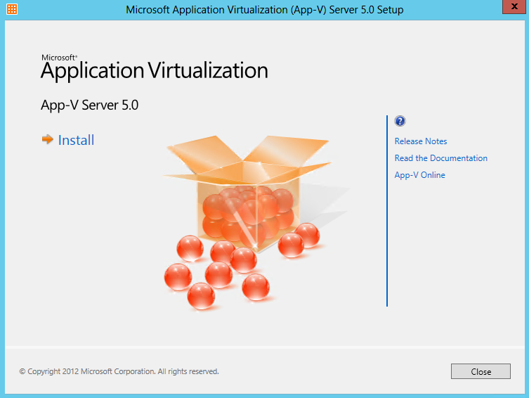
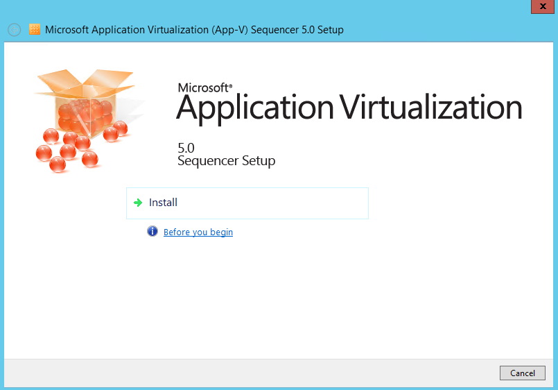
- First of all install the APP-V Sequencer
- Click Install
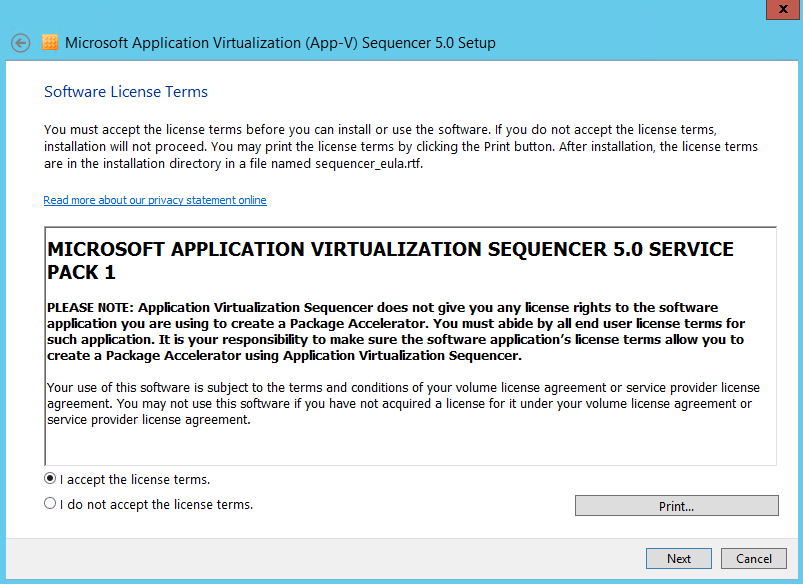
- Accept the License Agreement
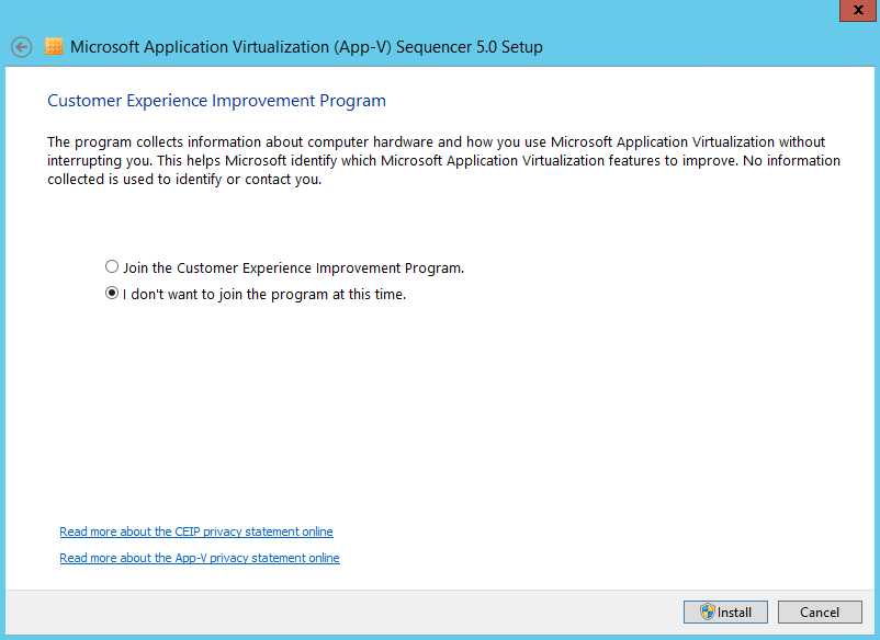
- Choose whether to join the Customer Experience Improvement Program and click Install
- Here Setup should have completed successfully
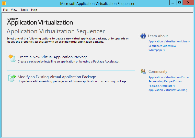
- Hold down the Windows key and Q to get the aero screen showing all your applications and click on Microsoft Application virtualization Sequencer which will then pop up the box below
- Click Create a new Virtual Application Package
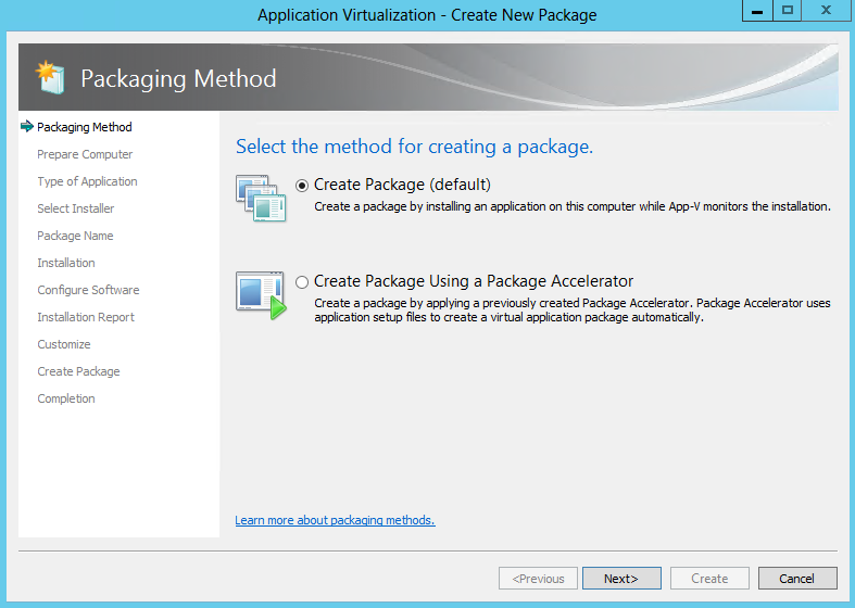
- Select Create Package and click Next
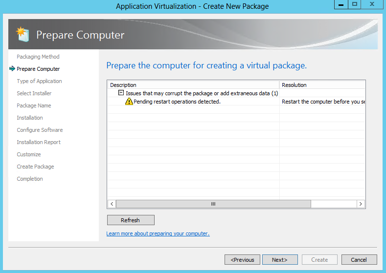
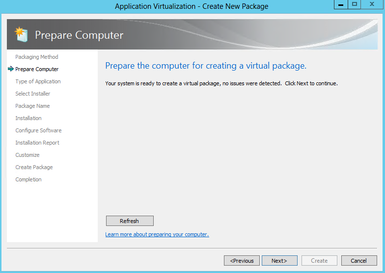
- Next, the Sequencer examines the current operating environment to evaluate running processes or conditions that are in place (e.g. the Sequencer has not been reverted to a clean state after a previous sequencing operation, or there are pending reboot operations) that might prevent successful sequencing. See example below
- It should now look like the below when everything is ok
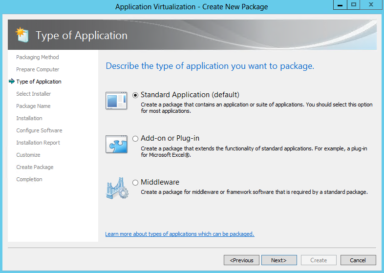
- Choose the type of application. Click Standard Application (default)
- Standard Application (Default) Select this option when sequencing a single application or suiting multiple applications into the same virtual application package
- Add-on or Plug-in. Select this option when sequencing multiple applications in separate virtual application packages and linking them using a Connection Group. This option can also be used when packaging Add-ons or Plug-ins for locally installed applications like Internet Explorer.
- Middleware. Select this option when sequencing multiple applications in separate virtual application packages and linking those using Connection Groups. This option will first create the application package for the middleware component and then create the second virtual application package that will contain the primary application
- Click Next
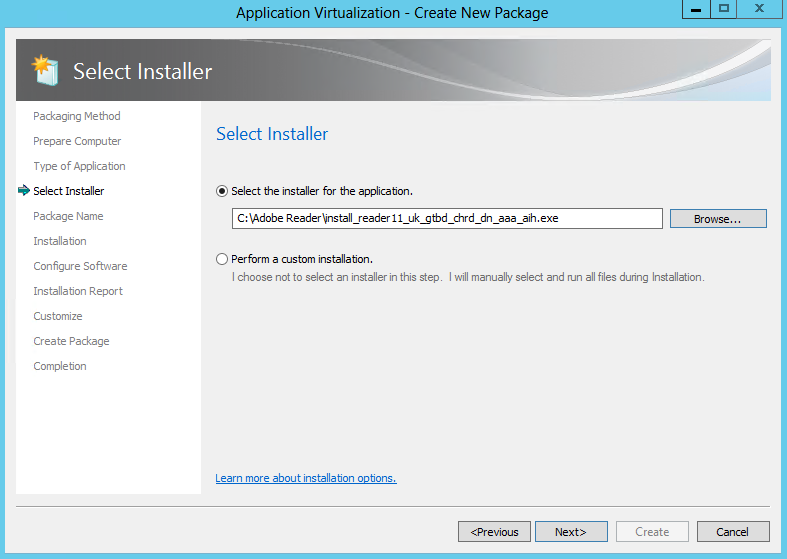
- Select the Installer for the application is the first option. An “installer” can be any executable file designed to install the desired application. The Sequencer will automatically launch the installer when it activates monitoring.
- Alternatively, “Perform a custom installation” can be selected. This option causes the sequencing wizard to enter monitoring and then wait for manual launching installation tasks. This option is often useful when sequencing applications that may not have an install or setup file such as applications that copy from a network share

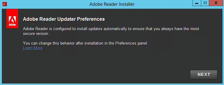
- I am going to use the Adobe Reader 11 installer
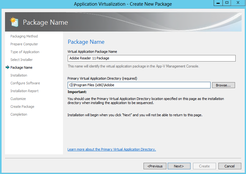
- Select a package name, typically something descriptive of the vendor, software and version. This name is independent of the Primary Virtual Application Directory, but should be noted for saving the package. Saving the package in a directory named for the package name is recommended. At the package name screen, select the Primary Virtual Application Directory.
- The Primary Virtual Application Directory is the directory that will contain all files for the sequence. It is recommended to define the application’s default installation directory (example C:\Program Files (X86)\directory) as the Primary Virtual Application Directory.
- Click Next
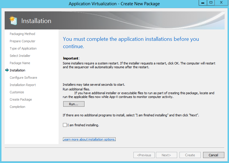
- When multiple installers are required to create the package, click Run after the completion of each installer, select the next installation program, or manually launch the installer until all installers have been successfully installed.
Once all installations are complete, select the I am finished installing check box and click Next.The installer popped up automatically or you can manually click on your exe to run the software
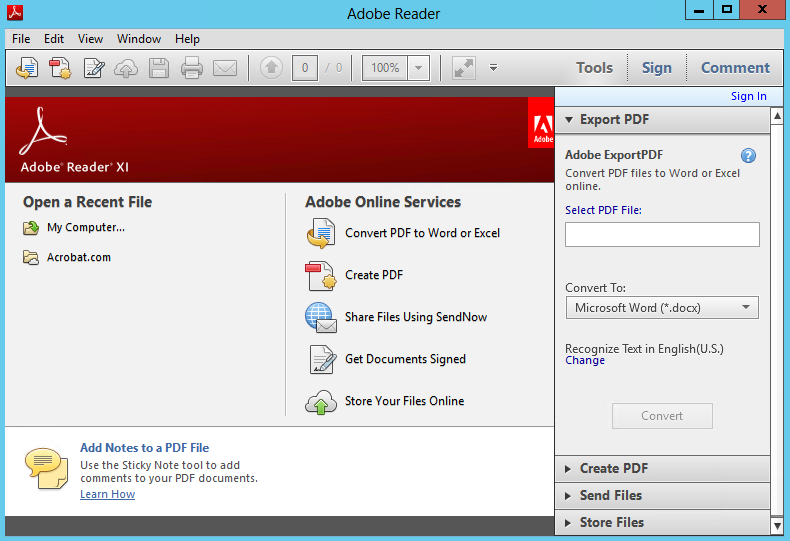
- The application you selected should start automatically
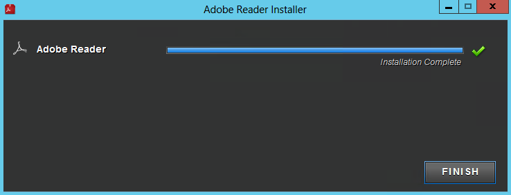
- Click Finish when the application has finished
- Put a tick in I am finished installing
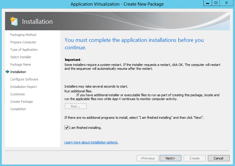
- The below screen will run
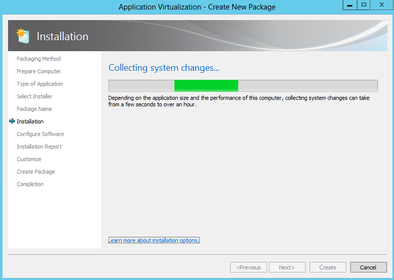
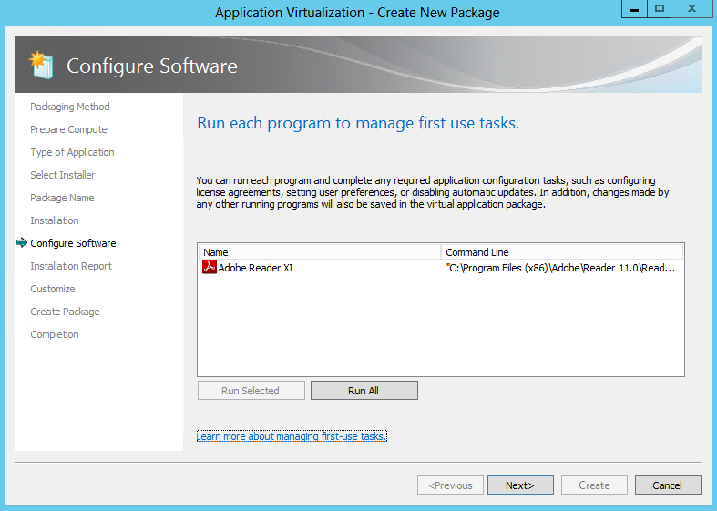
- Many applications have first-run tasks such as accepting license agreements, etc. At this stage, execute the application(s) at least once by selecting the application and clicking the “Run Selected” or “Run All” buttons (multiple executions are recommended to ensure any second-run tasks are executed). Also, it is during this execution that any applicable application configuration changes should be made.
- Note: This screen is also running in monitoring mode. It is possible to manage the tasks for programs that are not listed on this page by launching them outside of the Sequencer using Windows Explorer
- Then the following screen – Configure Software will appear
- Example License Acceptance from Adobe on first run
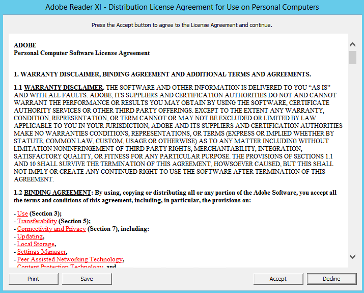
- Click Next
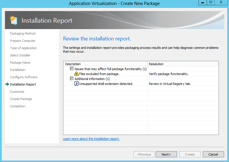
- Review the Installation Report
- The Sequencer detects common issues during sequencing. The Installation Report page of the wizard displays diagnostic messages categorized into Errors, Warnings, and Info depending on the severity of the issue. Double click an item in the report to view detailed information about the issue as well as suggestions for resolution. Messages from the system preparation report as well as the installation report are summarized upon package completion and are saved along with the package in a report.xml file.
- Excluded Files
- Drivers
- COM+ System differences
- SxS Conflicts
- Shell Extensions
- Files or registry entries that were not captured during monitoring
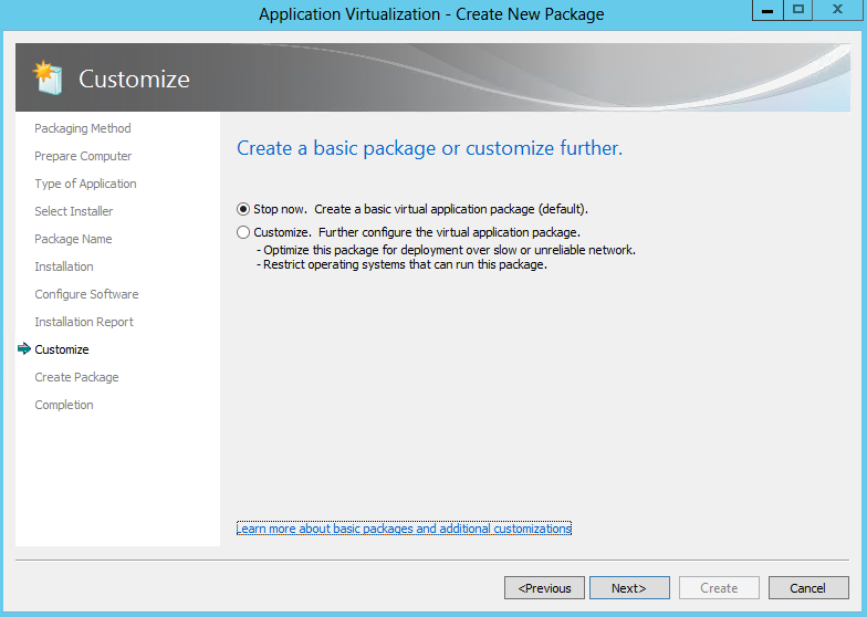
- Choose Stop now if the sequence will not benefit from further customization and select Create.
- However, often there are other steps remaining under the Customise Option such as:
- Splitting the package into feature blocks to reduce the streaming requirement and save bandwidth.
- Selecting additional client operating systems that will be permitted to receive this package.
- Changing shortcuts and file type associations.
- Modifying registry settings and adding and deleting files in the package.
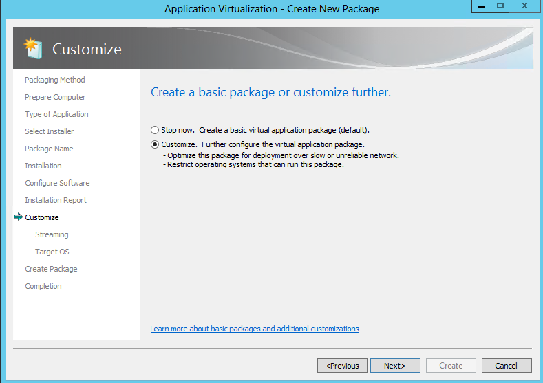
- When additional customization is required select Customize and Next to continue the sequencing process and allow additional changes prior to the creation of the package.
- Choose Customise
- Prepare for Streaming
- Feature blocks are designed to optimize the applications for streaming (if applicable), creating a minimum launch threshold that allows launching larger applications as soon as enough of the package has been downloaded and does not require downloading the entire package. This enables users access to applications more quickly upon deployment.
- Feature blocks also reduce the total network bandwidth used when launching the application for the first time and saves hard disk space on the client by leaving less-used data on the server until it is specifically called by the user.
- Creating feature blocks is recommended unless the deployment method for virtual application packages is only completed with System Center Configuration Manager for Download Locally and Run option or via MSI for standalone mode clients.
- At the Prepare for Streaming screen, feature blocks are created based on individual, selection of, or all applications
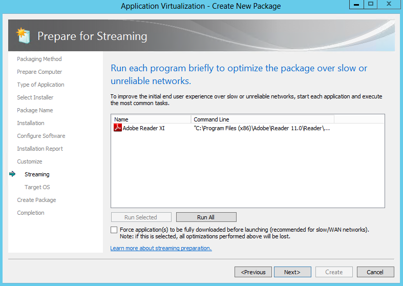
- Select and run each shortcut from the package that users execute in typical day-to-day operations. Then, perform the common tasks that typical users perform within each particular application during normal operations.
- During this process, the Sequencer tracks which specific pieces of the package’s resources are being executed and includes them in the primary feature block. When a user launches the application for the first time, the App-V client will stream and cache just the data within the primary feature block over the network and will launch the application.
- Any pieces of the package not included in the primary feature block are placed in the secondary feature block and reside on the server or storage location until specific resources from within the secondary feature block are called by the App-V client. Those pieces are streamed on-demand and cached on the client.
- Clicking ‘Next’ without launching any shortcuts enables the entire content of the package streaming and cached “on-demand” on the App-V client. Typically, this is done for very small application packages if streaming the entire package does not cause any network bandwidth concerns.
- Normally, the client launches the application after the primary feature block has been downloaded to improve launch time. By selecting the “Force application(s) to be fully downloaded before launching” option, the client will be forced to wait until all blocks of the virtual application package have been downloaded before launching the application. This is useful when clients may be running this package over slow WAN links.Launch your application and then close it again
- Launch Adobe and make any modifications then close this again
- Now what Operating systems do you want to allow this to run on
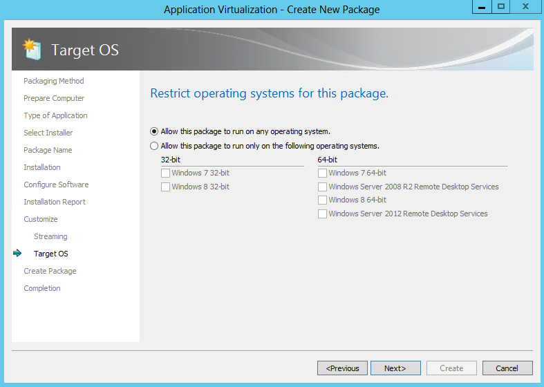
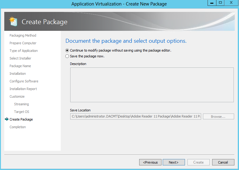
- You can now continue to modify the package or save the package now. For the purpose of seeing all the options, click to continue
- You should now have a Package completed screen

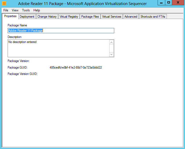
- The next screen which is the package editor, is composed of several tabs that enable further configuration modification prior to saving the package. These tabs include options to modify the various settings
- Properties
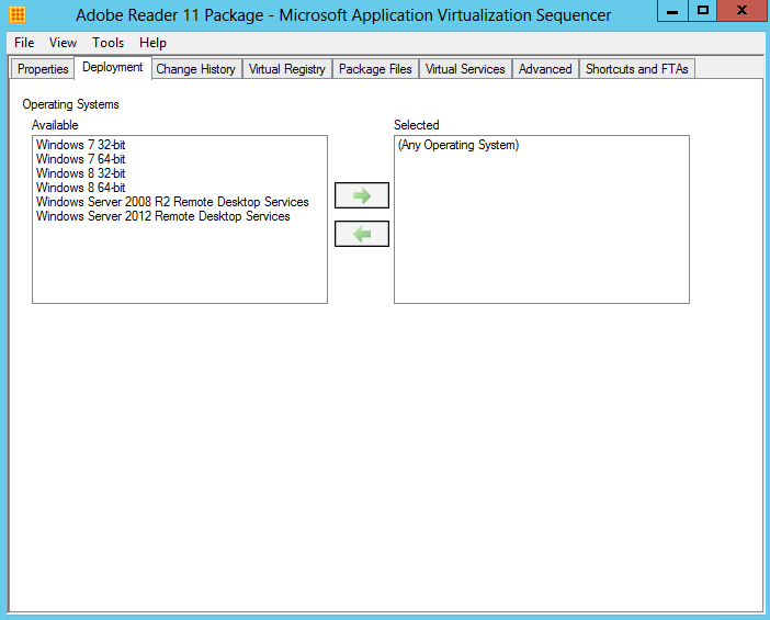
- Deployment
- Change History
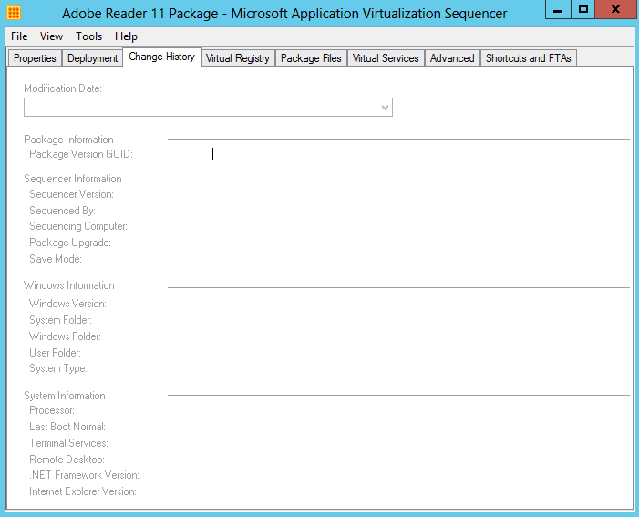
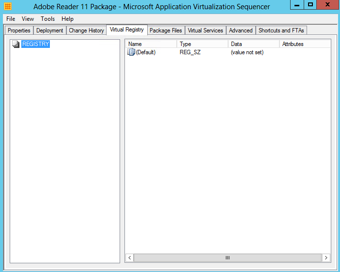
- Virtual Registry displays the current virtual registry configuration and allows for deleting or renaming existing keys and values as well as adding new keys and values in both the HKLM (Machine) and HKUSERS (Users) hives. Where the same registry key may exist on the local system as well as in the virtual application package, the virtual key can be configured to either merge with the local configuration or override the local configuration
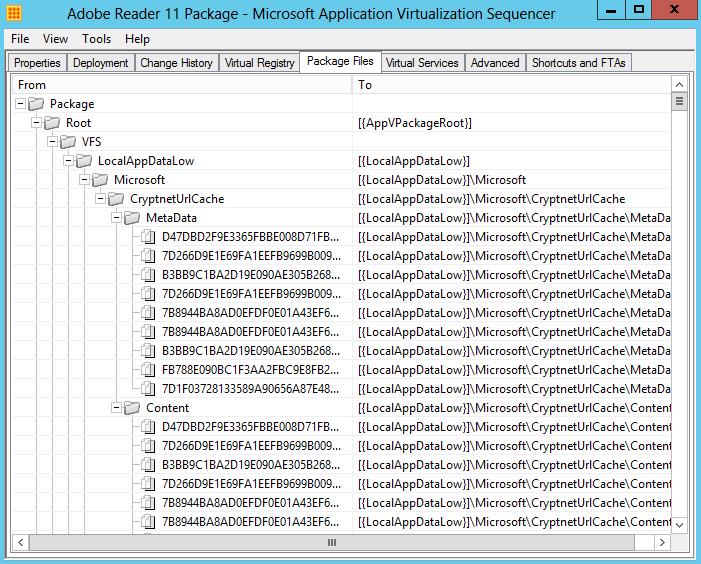
- The Package Files tab displays the current list of files and folders added to the package and allows for the addition or deletion of files. However, this interface should not be used to add or remove files in the package if the package has previously been optimized for streaming by way of creating feature blocks
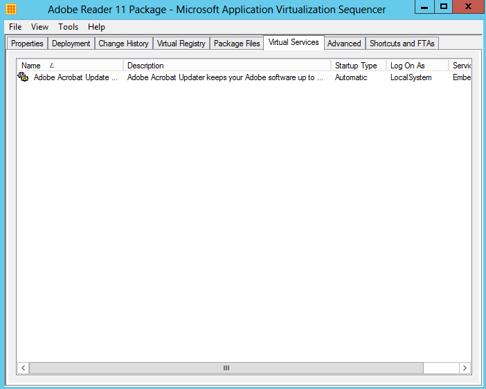
- The Virtual Services tab displays the current configuration of virtualized application services and allows for changing the Startup Type, Log On and Dependencies configuration of virtualized services.
- Note: The services tab is read-only. In order to disable a virtual service, set the service’s properties during monitoring using Services.msc or by utilizing a dynamic configuration file post-sequencing.
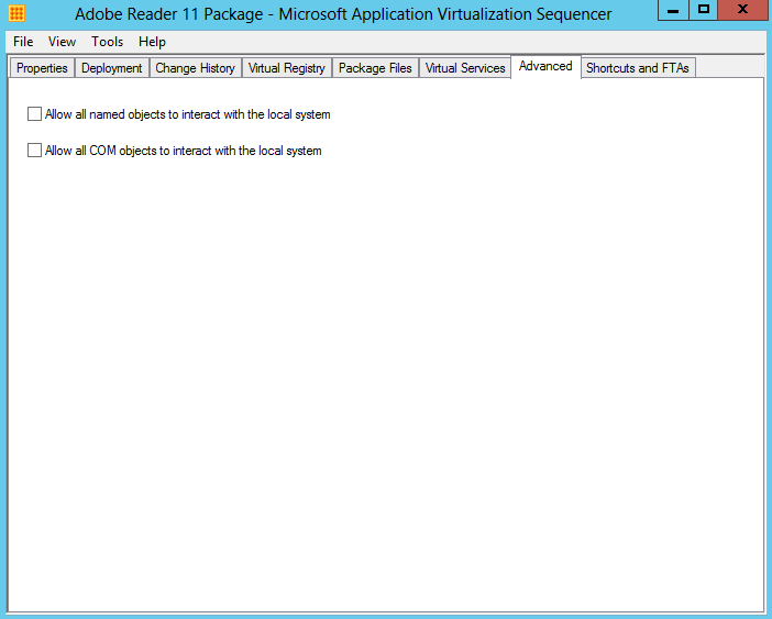
- The Advanced tab provides an option to enable visibility of named and COM objects in an App-V package to the local system to improve the usability of some application functions. Local system visibility may be useful for such tasks as virtualizing legacy versions of Microsoft Outlook
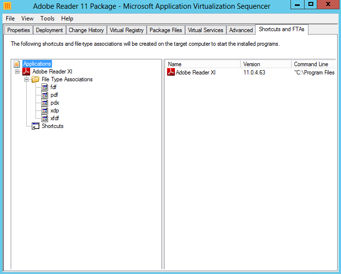
- The Shortcuts and FTAs tab provides the ability to customize the Shortcuts and File Type Associations for the applications identified during monitoring. Applications may have to be added or removed from this list, based requirements for the final package. In addition, with web-based applications it is often necessary to add Internet Explorer as an application where the web-based application requires launching Internet Explorer as a dependency.
- Each application can be modified to change the name, icon, file type associations, and locations for shortcuts on destination computers.
- When you are finished making customizations, select the File pull-down menu and select Save or Save As to save the virtual application package.
- As a recommended best practice, create a new folder for the package using the Package Name and save the package in this folder. Once saved, copy the package folder to a preferred package repository.

- It should show you the below screen!
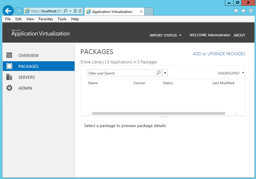
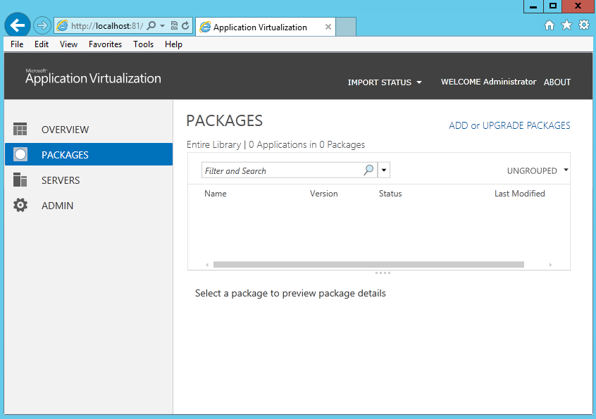
- Next you need to open up the App-V 5 Web Console and connect to App-V
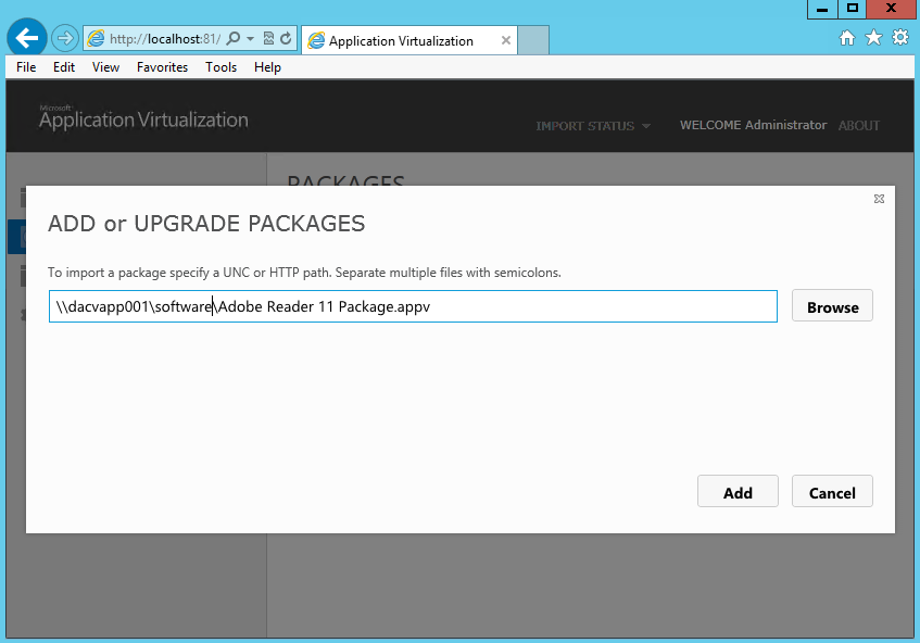
- Click Add or Upgrade Packages
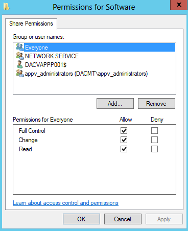
- Type in the Share or URL name and click Add. I set up a share called software which contains my Adobe App-V Package.
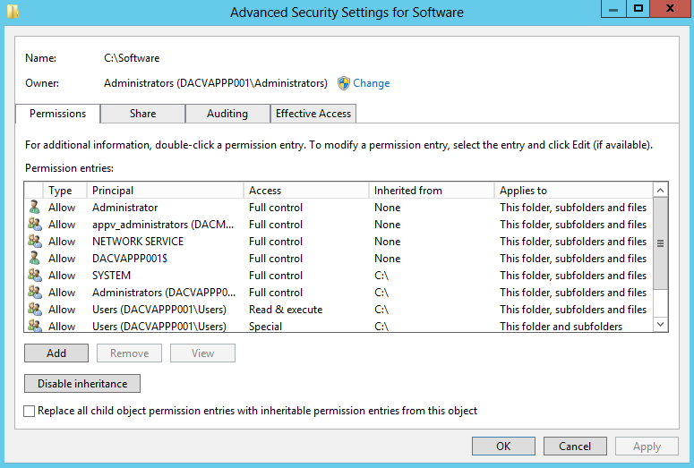
- You must make sure you have added the App-V Server name e.g. dacvapp001$ to the Share and NTFS Permissions of the shared folder
- and
- Now add your package via UNC or HTTP Path
- I also found instead of putting my server name, I could put localhost for the servername
- If the package import is successful, you will see the below
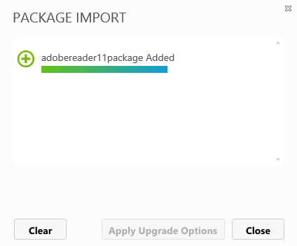
- You will then be back to the main console showing you your added package
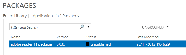
- Underneath here you can see the following
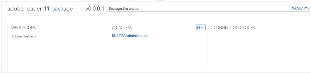
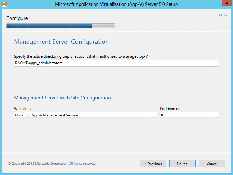
- Click on AD Access and add the AD Groups you want to have access. As you can see I have just added my Administrators Group as this is a test lab
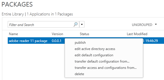
- Now you need to right click on your App and select Publish
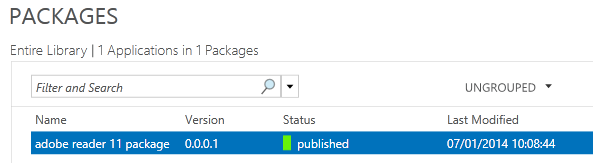
- It should now say Published
- Next… In order to stream the app to a client, we need to have the App V 5 Client installed on a VM so I have another VM where we will install this software as per below instructions
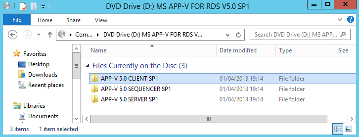
- Attach the App V 5 ISO to your machine and click on APP-V Client 5 SP1
- The installer will start and will install any pre-requisites as per below
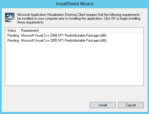
- You are now ready to install the client
- Follow the Install Wizard
- You should then see the following screen when complete
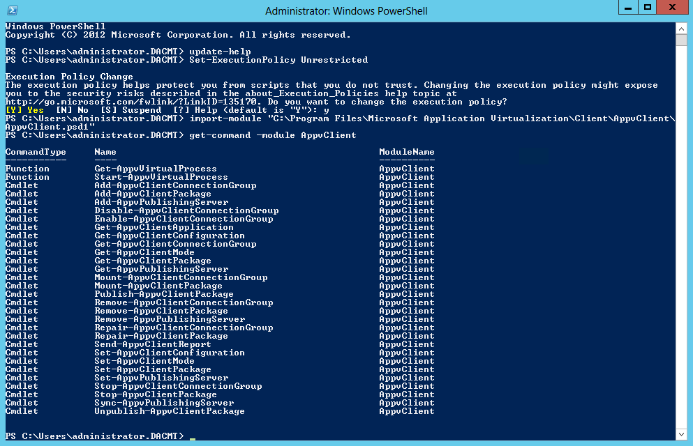
- Next Open PowerShell as an Administrator and type the following commands
- Update-Help
- Set-ExecutionPolicy Unrestricted
- Import-Module “C:\Program Files\Microsoft Application Virtualization\Client\AppvClient\AppvClient.psd1”
- Get-Command – module AppvClient
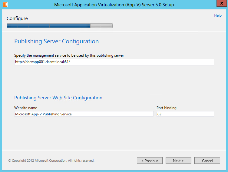
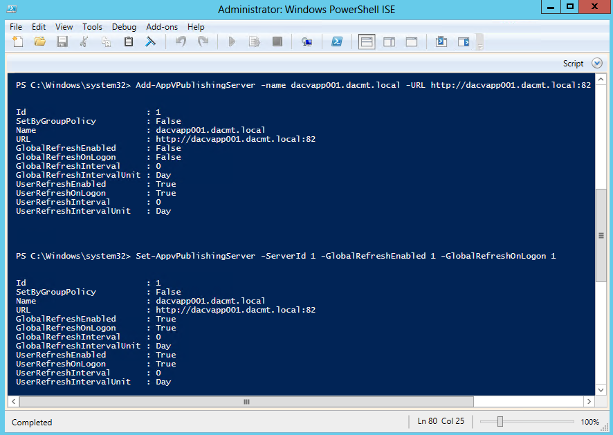
- Add-AppVPublishingServer -name dacvapp001.dacmt.local -URL http://dacvapp001.dacmt.local:82
- Set-AppVPublishingServer -ServerID 1 -GlobalRefreshEnabled 1 -GlobalRefreshOnLogon 1
- Close PowerShell
- Restart the Server
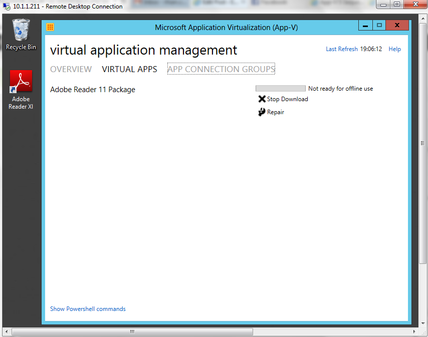
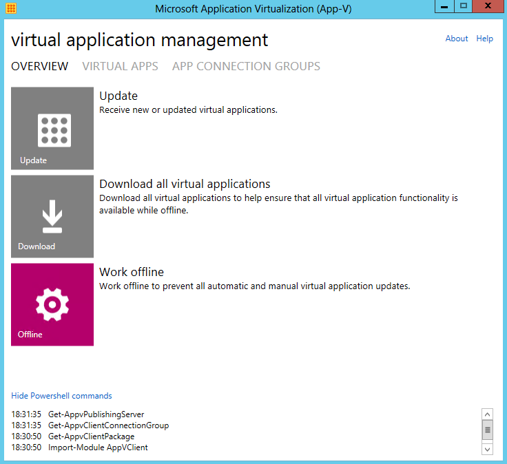
- Open the AppvClient
- Click Update and wait a few moments
- Next Click Virtual Apps on this screen to check that your package is there
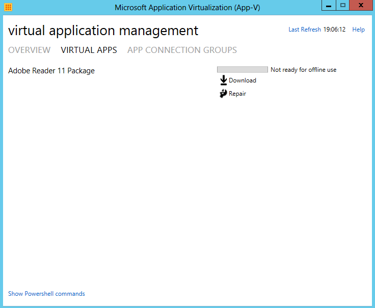
- Click Download
- Lo and Behold, if everything is ok then you should see the Adobe Reader icon on your desktop
- Go and have a glass of wine phew! 😉